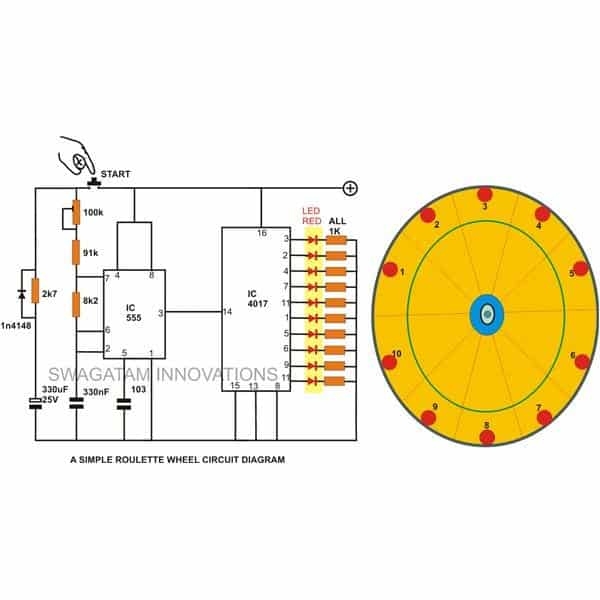
This is an example of a very basic 10 LED roulette wheel circuit. When the button is pressed, the LEDs begin to rotate (sequence) at full speed and then progressively slow down until they stop at a certain, randomly chosen LED.
The length of time the push is kept turned on by the finger determines how randomly the choices are made.
The roulette application is extremely reliable since the final LED position may be changed by even 0.1 seconds.
10 LED Simple Roulette Wheel Circuit Diagram


Wheel of Fortune

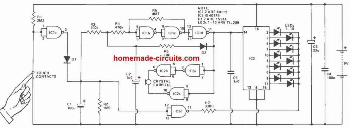

The circuit for the Wheel of Fortune may be divided into four distinct stages: the voltage-controlled oscillator, the touch-sensitive/monostable circuit, the LED display stage, and the wheel sound audio stage.
Because resistor R1 keeps the IC1a input high when the gate is switched to the "off" state, the output of the gate—which is configured like an inverter—stays low and C1 is discharged.
When the touch pads are connected, the gate's output becomes high, which charges C1 through D1.
Since D1 is now reverse biased, C1 is prevented from discharging into this gate immediately as the finger is removed from the touch pads and the IC1a output drops again. Instead, C1 progressively discharges via R2. The components of IC1b, c, and d combine to form the VCO.
This wheel of fortune circuit really creates a series of fixed-period negative pulses separated by "voids" whose durations may be adjusted by varying the control voltage.
The circuit ceases to oscillate promptly as the control voltage, or the voltage across capacitor C1, drops below a predetermined threshold, which is approximately one-half the supply voltage.
When the touch pads come into contact with a finger, capacitor C2 will start to gently charge if it is expected that the voltage across capacitor C1 will increase to the supply voltage level.
The schmitt trigger produced by IC1a and b receives the C2 voltage through R4.
The IC1d output, which is in charge of buffering and inverting the schmitt's output, goes low when the voltage applied on the schmitt crosses its upper switching maximum.
This compels capacitor C2 to begin rapidly discharging via the relatively low impedance path that R6 and D2 have supplied.
Capacitor C2 can keep charging as long as the voltage across it stays over the lower threshold of the Schmitt IC1d output, which is reached when the voltage across it drops.
The voltage across C1 determines how long it takes for the C2 voltage to reach the Schmitt's trigger level.
As a result, the VCO starts producing a high frequency as soon as the voltage across capacitor C1 is high enough to induce capacitor C2 to quickly reach the activation stage.
The frequency continues to decrease as the voltage across C1 gradually decreases.
In addition to operating the attached LED ring through IC3, the output voltage obtained from the VCO is further sent to IC2a, b, and c, which provide the "tick-tick" sound that simulates the sound of a roulette wheel rotating.
The "clicking" sound produced by the crystal earpiece is controlled by a bridge circuit.
This effectively doubles the voltage given to the transducer, which helps to produce a louder audio output by applying the formula P = V^2/R.
IC3 powers the LEDs; its cathodes are seen connected to the IC2d output via R7.
This gate's output typically remains high but only drops until the voltage across capacitor C1 surpasses the half supply level.
The wheel of fortune LED display is thus activated for a time window that is somewhat longer than the oscillation speed of the VCO when the IC3 outputs are in the active high region.
Capacitors C3 and C4 allow the supply voltage to be disconnected, while capacitor C5 shields the circuit from any RF interference that would negatively impact its operation.
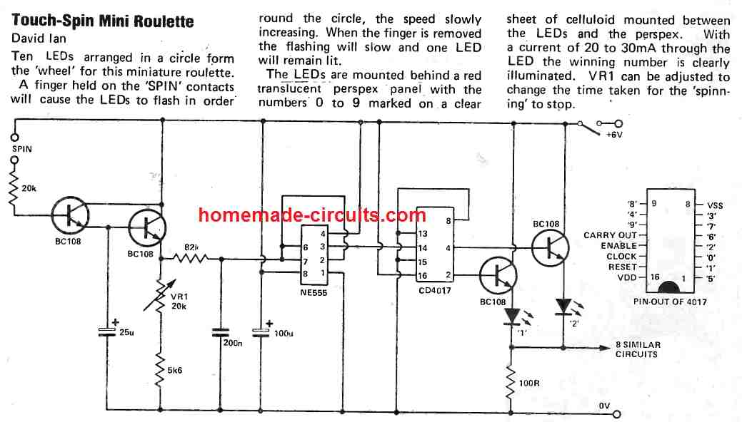
Simplest 8 LED Roulette Wheel Circuit

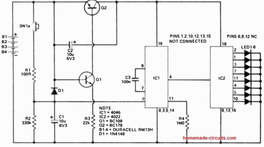
The description that follows will help you understand the functioning details:
As a Johnson counter, IC2 turns on the LEDs one at a time with each clock pulse.
The phase-locked loop's VCO portion, or IC1, produces the clock signal.
The voltage connected to pin 9 determines the frequency generated by IC1.
Capacitor C1 charges via resistor R1 in proximity to the positive supply voltage when the spin button is pressed.
After the button is released, resistor R2 causes the charge to progressively fade over a few seconds.
This causes the light to quickly rotate around the LED circle while the button is depressed.
The spin gradually slows down until it stops altogether when the button is released.
The function of transistors Q1 and Q2 is to cut off the power supply while the casino is not in use.
Q1 conducts current via resistor R3 when the spin button is pressed, activating Q2 and facilitating the circuit's function.
When the button is released, capacitor C2's negative side rises to almost the entire supply voltage. The base current given to Q1 causes C2 to gradually charge, thereby lowers the voltage over R3.
Q1's capacity for consuming enough current starts to decline after about a minute, which makes Q2's powerful conduction weaker.
Q1's base voltage declines as a result of a little dip in Q2's collector voltage, which also reduces Q1's current flow.
The casino enters an inactive phase whereby just Q2's leakage current is pulled until the wheel button is hit again after this regenerative mechanism quickly turns off the current.
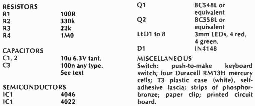
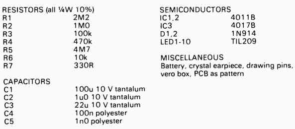
Parts List