
Let's examine how a mains 220V or 120V operated high voltage as well as low voltage protection circuit may be constructed using only a few transistors. Up until now, we have studied an IC version of the circuit.
Installing a very basic circuit in the home's electrical system might much assist in mitigating the problem.
High Low Voltage Cut Off Circuit Using Transistors
You'll be astonished to learn that a simple circuit with only a handful of transistors and other passive devices may be constructed to provide the aforementioned security measures.
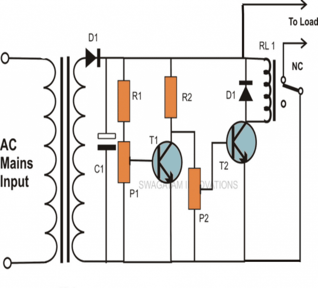
The image depicts a very basic setup in which T1 and T2 are rigged in an inverter configuration, i.e., T2 operates in the opposite direction of T1. Kindly see the circuit schematic.
Put simply, T2 turns OFF anytime T1 conducts and vice versa. Through preset P1, the sensing voltage—which is obtained from the DC supply voltage itself—is sent to the base of T1.
By using the preset, the circuit is able to accurately identify when to perform control operations and trigger thresholds.
Tips to Set the Preset for Automatic Cut off
The purpose of P1 is to detect high voltage limits. T1 is first kept off while the voltage is inside the safe window. This permits the necessary biasing voltage to go via P2 and reach T2, which keeps T2 turned on.
In order to ensure that the connected load gets the necessary AC voltage, the relay is likewise maintained engaged.
Nevertheless, if the 220V or 120V AC voltage surpasses the permissible limit, and the detecting sample voltage at the base of T1 climbs beyond the specified limit, T1 quickly switches ON and grounds T2. As a result, T2, the relay, and the associated load are all turned off.
Consequently, the system's design prevents the load from receiving the hazardous voltage and protects it as it should.
Assume that the mains voltage drops drastically. In this case, T1 has already been turned off, and T2 also ceases to operate because of P2's parameters, which are configured to cause T2 to cease operating when the mains input falls below a predetermined dangerous level.
This causes the relay to turn off yet again, shutting off the load's power and triggering the necessary safety precautions.
The circuit activates only for voltage levels over 260V and below 200V, or greater than 130V and under 100 V for 120 V typical supply inputs, despite the circuit's reasonable accuracy due to an excessively broad window threshold value.

Because of this, those searching for controls that can be adjusted to their own preferences and cut-off points that are just exact may find that the circuit is not particularly helpful.
It might be necessary to substitute a few opamps for the transistors in order to accomplish the above
Parts List
- R1, R2 = 1K = 2
- P1, P2 = 10K =2
- T1, T2 = BC547B =2
- C1 = 220uF/25V = 1
- RELAY = 12V, 400 OHMS, SPDT = 1
- D1 = 1N4007 = 1
- TR1 = 0-12V, 500mA = 1