
The LM63635 integrated circuit may be used to construct an adjustable switching buck regulator that will transform a 32V DC input into a variable 1V to 20V DC output.
Main Features of LM63635
With careful engineering, the LM63635-Q1 is a novel synchronous peak-current-mode buck converter that may be used in a wide range of automobile uses.
Depending on the exact needs of the load, this 1V to 20V adjustable buck converter regulator switches between pulse frequency modulation (PFM) and pulse width modulation (PWM) with ease.
It skillfully functions in PWM mode under high loads, keeping the switching frequency constant.
As the load decreases, on the other hand, the regulator smoothly transitions to PFM mode with diode modeling, enabling discontinuous conduction mode (DCM).
By lowering the input supply current, this clever transition successfully maintains efficiency.
This device's primary characteristics include a variety of functions:
Adaptable switching frequency to meet the needs of your application.
The capacity to switch on Forced PWM mode (FPWM) when needed.
Synchronization of frequencies to improve accuracy.
Freedom to select the ideal output voltage based on your needs.
How to Set the Output Voltage
The input state of VSEL controls the output voltage of the LM63635D-Q1. In a situation where a fixed 5-V output is required, the output capacitor could be hooked up to the FB input and VSEL to VCC.
The LM63635C-Q1 variant requires an extra feedback divider, though, if a 1V to 20V DC programmable output voltage is required from a 32V source. This divider network is made up of RFBT and RFBB, as shown in the circuit diagram below, which locks the feedback loop between the converter and the output voltage.

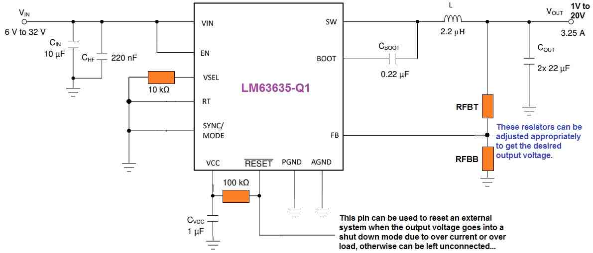
In order to link the VSEL input to ground in this case, a 10-kΩ resistor is used. By keeping the voltage on the FB pin at the identical magnitude as the internal reference voltage, that is set at 1-V, the converter guarantees the control of the output voltage.
A trade-off between limiting excessive noise disturbance and minimizing overloading on the output is the resistance of the divider.
While smaller resistance values lessen noise sensitivity, they also result in lower efficiency at minimal loads. The largest number that may be used for RFBT is 1 MΩ, and 100 kΩ is the suggested amount. A feedforward capacitor must be placed across this resistor if 1 MΩ is selected for RFBT in order to provide an adequate loop phase difference.
The following formula, with VREF normally adjusted at 1 V, is employed to find the suitable value for RFBB after RFBT has been established.
RFBB = RFBT / [(VOUT/VREF - 1)]
In order to achieve a variable 12V DC output from a 32V DC input source, the feedback potential divider network may be correctly configured by solving the above calculation.
Reference: LM63635D-Q1 Datasheet