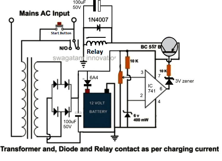
You can build an auto cut off battery charger circuit using a single IC 741 in a comparator configuration. Let's learn how?
Understanding the Circuit for a Single Op-Amp Charger
This description concentrates on a circuit design, which charges big batteries using a single 741 op-amp. This is an explanation of how it works:
A transformer is used at the beginning of the circuit to reduce the AC mains voltage.
The transformer's AC voltage is changed into an unregulated DC voltage by a bridge rectifier.
The description omits discussing a filter capacitor that comes after the bridge rectifier for simplicity's sake.
On the other hand, in actual use, a capacitor (such as 1000uF/25V) positioned between the bridge's positive and negative terminals can enhance the DC output quality for battery charging.
The battery that is being charged is directly linked to this unregulated DC voltage.
The operational amplifier, or op-amp, used in the subsequent stage is a 741 integrated circuit set up as a voltage comparator.
While the battery is being charged, this op-amp measures the voltage and modifies its output at pin 6 accordingly.
Through a 10k ohm adjustable resistor (preset), pin 3 of the 741 op-amp is linked to the positive voltage source (either directly from the battery or the circuit's supply).
The 741 op-amp's output at pin 6 is controlled by adjusting this setting.
When the battery achieves its full charge voltage (about 14 volts), which normally corresponds with the transformer's output voltage under normal circumstances, the op-amp should ideally switch to a high output.
Using a voltage divider network, pin 2 of the 741 op-amp is set to a fixed reference voltage. A 6-volt zener diode and a 10k ohm resistor make up this network.
Relay Control Stage:
Relay driver stage is linked to pin 6 of the op-amp output.
Here, the main control element is a transistor (BC557).
Charging and Automatic Shut Off:
Initially, the circuit is activated by pushing the "start" switch. For starting power, this switch briefly bypasses the relay connections.
The battery voltage is sensed by the op-amp, and it will be low at this point. As a result, the output of the op-amp drops.
The relay is activated by the transistor (BC557), which is turned on by the 741 op-amp's low output.
Even when the "start" switch is released, the energized relay clamps its contacts, keeping the circuit powered. This permits the battery to start charging.
The op-amp senses a change in battery voltage as it rises during charging and gets closer to 14 volts.
After that, the 741 op-amp changes to a high level output.
The relay is deactivated when the transistor (BC557) is turned off due to the excessive output of the op-amp.
latching mechanism is disrupted when the deactivated relay shuts off power to the circuit.
Until the "start" button is pressed once again and the battery voltage drops below the predetermined 14-volt threshold, the entire circuit is off.
How to Setup the circuit
The setup procedure for this is rather easy. Initially, confirm that the battery is unplugged from the electrical system.
To activate the circuit, press and hold the "start" button. Holding down the button, crank up the 10k ohm preset resistor's resistance until the circuit hits the voltage threshold of your transformer, approximately 14 volts, at which point the relay almost trips (turns off).
Release the "start" button after the relay trips at the appropriate voltage. Now attach a partly discharged battery to the circuit's specified locations.
In the end, flip the "start" switch. The voltage applied to the circuit will be less than 14 volts since the battery has been completely depleted.
As previously mentioned, this will cause the circuit to latch and start the charging process.
Below is the circuit diagram for the proposed high current single op amp battery charger.