
This post discusses a few straightforward yet reliable BJT transistor tester circuits that may be utilized to determine if a transistor is good or faulty.
Simple Good or Not good Transistor Tester
Is your junk drawer filled with an odd assortment of obsolete BJTs? This simple tiny transistor checker circuit lets you know what to keep and what to discard.

Just identify the base, emitter, and collector pinouts of the transistor type, set the sliding switch to PNP or NPN, attach the component, and watch for the push buttons.
A push of PB1 will activate the LED in BJTs with medium to high gain. When you press PB2, the LED comes on.
A low-gain BJT is indicated if it doesn't light up at all or lights extremely weakly. To initiate the leakage test, hit PB2. The LED must be illuminated either very weakly or not at all.
Highly Accurate Transistor Tester using Op Amps
This op amp centered, extremely precise transistor tester may be used to rapidly evaluate whether a transistor is good or faulty, as well as whether it is PNP or NPN, provided you're aware of its pinout. Furthermore, a few typical breakdown categories are identifiable.
The construction prioritizes straightforwardness and ease of use, and a single PP3 battery can power it continually for almost a month. The tester can only test bipolar transistors; FETs cannot be tested with it.
Hitting the test button—which is actually the on/off switch—activates the tester, and a panel socket is used to attach the questionable transistor.
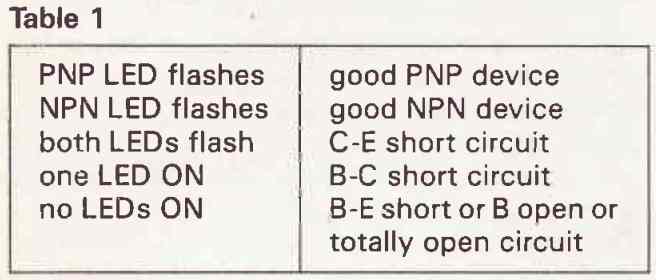
The two LED conditions provide the following the test results (Table 1).

Circuit Description
The tester applies varying bipolar signals in a common base circuit to the collector and emitter of the transistor being tested, causing current to circulate in the LEDs when the transistor is conducting.


There is a battery test button to help distinguish between an open circuit transistor and an invalid battery.
This button will cause both LEDs to blink in mimicking of a C-E short if the battery is in good condition.
The dual op-amp chip used by the tester is an 8-pin dual op-amp, or dual 741's equivalent (IC 1458 in my case). It may be replaced with a variety of pin-compatible devices, including the 353 twin J-FET amp.
LED Type
Ultimately, I used two green LEDs, labeled NPN and PNP, measuring 0.2 inches each, as the indicators. An earlier version used a red LED for PNP and a green LED for NPN, which looked much nicer. However, if you want a dual-color display, you must use intensity-matched LEDs.
I abandoned up on the project when I realized that my new red LEDs consumed a lot more current than the green ones.
As an alternative, use red and green LEDs with an identical overall light output (calculated in mA and mcd: millicandelas). Tested intensity-matched LEDs tend to be more costly.
This is critical since once the battery is installed, the second LED could illuminate very weakly if a good transistor is being tested (due to reverse conduction) if the proper one is relatively dim.
That might be confusing.
Setting up Procedure
There are two possible configurations for the BJT tester: a straightforward setup and a more intricate yet reliable one.
In both cases, the trimpot RV1 is changed until the circuit operates as required after imitating a C-E short by pushing the battery test button.
The two LEDs should blink in unison at around 3Hz. If not, you have probably committed a mistake of some sort. Proceed, supposing they do.
Using an assortment of previously identified ideal transistors, the easiest technique is to adjust RV1 until the proper response is achieved for all devices.
A popular set consists of BC184, BC274 (high gain NPN and PNP tiny signal), TIP31, TIP32 (3 A NPN and PNP medium gain power), and TIP3055, TlP2955 (15 A NPN and PNP low gain power).
The theoretical intermediate place is occupied by the RV1.
One transistor at a time is inserted into the socket, and the test button is then depressed.
After this, RV1 is gradually adjusted until the LEDs show the correct sequence. The transistors must be used in precisely this order: first, fine-tune the BC184 and BC214 until the tester shows that both are correct; next, fine-tune the TIP31 and TIP32; and last, calibrate the TIP3055 and T1P2955 to the lowest possible level.
The correct result should then be obtained by double-checking with any randomized transistor.
The disadvantage of this setup method is that it does not take into consideration performance drift with aging of the tester battery.
A new PP3 may produce as much as 9.6V in a circuit with minimal current usage like this one.
The tester should run on just one battery for as long as possible—let's say down to about 8V, so that's as low as we really could.
How to Check Transistors Directly on the Circuit Board
Transistors may be serviced while they are still placed into the circuit board thanks to this ingenious small checker circuit.

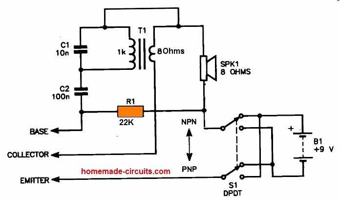
The leads labeled Base, Emitter, and Collector could be connected to hook-type connectors that attach to the transistor's legs on the circuit board or wherever it is situated.
The circuit functions similarly to a basic feedback audio oscillator and includes the base-emitter feedback of C2 and the secondary of the transistor audio output transformer T1.
The oscillator starts working and the speaker produces an audio output as soon as a good transistor is found. Should the identified transistor be defective, the speaker will not produce any sound, signifying a malfunctioning transistor.
The basic bias is given by the R2. Any speaker of a suitable size will do; in fact, the impedance of the speaker is not that important. The speaker might be a little 50 mm kind.
Multi-purpose BJT, JFET, MOSFET Tester Circuit
With the use of this practical transistor tester, one may rapidly ascertain the proper pin or terminal orientation and test the functioning of an NPN/PNP, JFET, or (V)MOSFET.

There are six possible associated arrangements for a three-pin BJT or FET, but only one of them will probably be the best.
This global transistor tester circuit concurrently performs a useful study of the transistor and provides a simple and reliable way to identify the correct transistor configurations.
Circuit Description
The transistor in the tester circuit alone, when combined with the transistor-under-test (TUT), creates an astable multivibrator circuit.

The tester has five testing slots that are near to one another and are identified by labels:
B/G - C/D - E/S - B/G - E/S
This setup enables the examination of the devices illustrated below using the aforementioned configurations:
- Bipolar transistors, in reverse order: BEC / ECB / CBE and EBC / BCE / CEB.
- SGD, GDS, and DSG are the opposite kinds of unipolar transistors (FETs): GSD, SDG, and DGS.
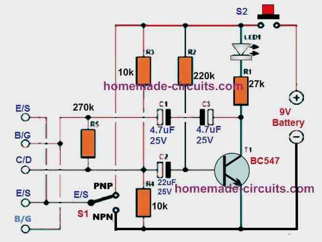
Assuming the transistor being tested is connected correctly, the astable multivibrator stage of the circuit oscillates and flashes a bright white LED (Figure 1).
When the transistor's E and C pins are switched, the LED may still flash, but it will flash more quickly.
This proves that some types of BJTs can still operate with the emitter and collector leads switched, perhaps with less desirable efficiency compared to if they are configured normally.
How to Test JFETs
It could only be possible to reliably identify the gate pin when examining JFETs having symmetric source and drain structures; the source and drain pins could even be switched.
Utilizing resistors R3/R4, the load resistance of the transistor under test is built like a voltage divider circuit with half the supply voltage. This makes it possible for a regular switch (S1) to switch from N(PN) to P(NP).
Transistor Tester with LED Indicator
The equipment under test is properly positioned when an LED starts to flash! An erroneous setup or a dead, blown BJT is indicated if the LED stays off or stays ON all the time.
This circumstance may also suggest that the device under examination isn't a transistor at all.
The object may be, for example, a triac, an SCR, or a 3-pin voltage regulator.
Transistor Tester with Buzzer Indicator
The second version of the universal transistor tester, shown in the following picture, uses a piezo buzzer in place of the LED indication.
In this design, the frequency-determining capacitor value is significantly lower than in the LED version in order to raise the oscillation frequency and produce an audible sound.
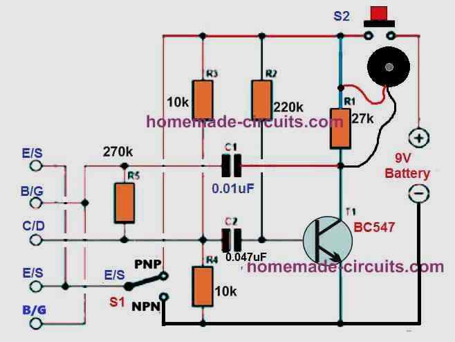
A low-pitched buzzing sound produced by the buzzer indicates that the transistor has been placed correctly and is functioning flawlessly.
If the buzzer doesn't make any noise, either the BJT or the FET being tested isn't installed correctly, or it can be dead.
Soon as the transistor is connected, the push button enables you to concurrently turn on the circuit and inspect it.
Using a little piece of Veroboard, the full circuit can be easily accommodated. One may acquire power source from a regular 9 V PP3 battery.
NPN/PNP Transistor Tester Circuit using IC 4069
Are you having trouble identifying which transistors in your garbage box are NPN and which are PNP? Absolutely no concerns!
This is a straightforward NPN PNP checker circuit that makes it easy to identify the appropriate components.

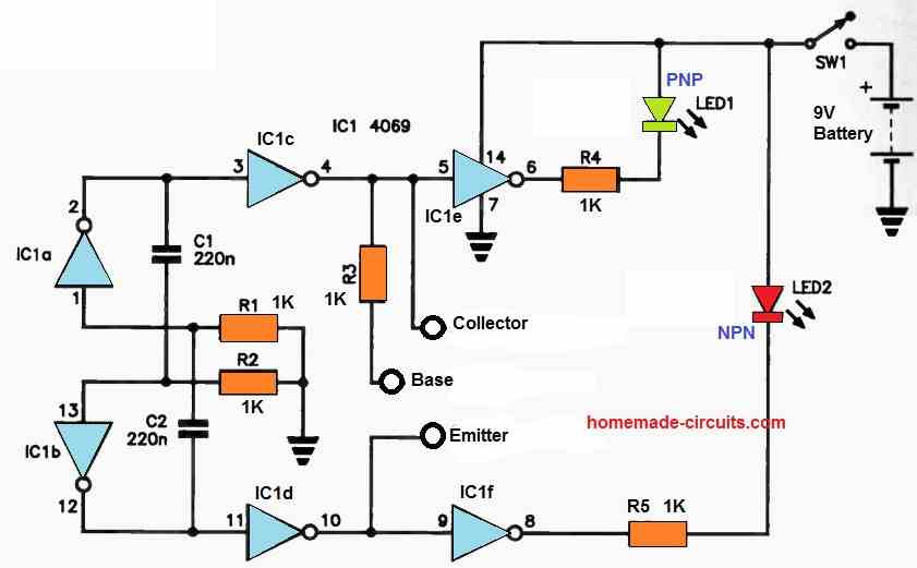
In this circuit, the NOT gate flip-flop powers many buffers, whose outputs supply power to the two LEDs.
Assuming an NPN device is attached, the transistor conducts each time the output of IC1c is high, causing just LED2 to light up and blocking the drive to IC1c.
The very high frequency oscillation of the IC1a, IC1b flipflop ensures that the only thing you see is the constant light from the LED.
Only LED1 illuminates when a PNP device is attached; this prevents the drive to IC1f since the device conducts anytime the output of IC1d is high.