
This circuit provides a practical, automated method of charging different lead-acid batteries, ranging in size from 1Ah to 1000Ah!
The 555 Timer IC is at the heart of the circuit.
This circuit's brain is the flexible 555 timer integrated circuit. Once again proving its effectiveness, the "single-chip solution" for electronics tasks is demonstrated.
Constructing with Simplicity
To build this amazing totally automated battery charger, all you need is a single 555 timer and a few passive parts.
Automated Recharge and Surveillance
The ingenious mechanism maintains the linked battery fully charged by automatically detecting its state of charge. The circuit will continually check the condition of the battery, so you may leave it attached indefinitely.
Intelligent Shutdown and Activation of Charging
To avoid overcharging, the circuit switches off the charging voltage when the battery achieves full charge. On the other hand, the circuit automatically begins charging again to raise the charge level when it falls below a certain threshold.
Working Description
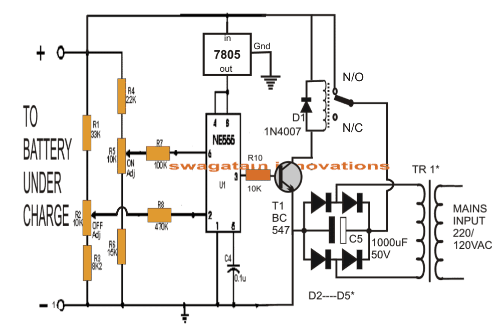
In this design, the 555 timer integrated circuit serves as a voltage comparator, acting as a watchdog. Two important battery points are continuously monitored by it: pin 2 (low voltage) and pin 6 (high voltage).
Automatic Charging Control: The 555 is made to flip its output (pin 3) high when the low voltage level (pin 2) voltage drops below a certain value, which is approximately one-third of the supply voltage. This starts the charging process.
The 555 has a built-in buffer that's helpful in keeping the state "high" even in the event that pin 2's voltage marginally rises.
But, the 555 instantly flips its output back to low (pin 3) if the battery voltage increases further and reaches a higher point (about two thirds of the supply voltage, as indicated by pin 6). This cuts off the charge to avoid overloading.
Configuring the Charge Levels: Resistors R2 and R5 in this circuit are modified to regulate the relay. The relay's purpose is to detect a 20% dip in battery voltage below its fully charged condition (detected by pin 2) and a 20% rise in voltage beyond that level (detected by pin 6), at which point it is supposed to switch on charging once more. This guarantees that the battery remains within a secure charging range.
Standard Power Supply: To supply power to the circuit, a standard bridge rectifier and capacitor arrangement is used.
Selecting Proper Diodes: At least twice as much current as the battery requires for charging should flow through the diodes. Generally speaking, the charging current itself ought to be about one-tenth of the battery's Ah rating.
The transistor (TR1) should be able to manage a current roughly equivalent to 1/10th of the linked battery's Ah rating, according to the preceding criterion.
Matching the Relay: The contact current rating of the relay should be determined by the current capacity of the transistor that has been selected (TR1).
This circuit design provides an easy-to-understand method for automatically charging batteries along with precise recommendations for choosing components.
Calibrating the Automatic Charger
Turn Off the Power: Make sure the circuit is totally off before starting.
Battery and Power Supply Simulator: Attach a variable power supply to the battery terminals of the circuit.
Establish Low Voltage Threshold: Modify the variable power supply so that it corresponds with your battery's intended minimum voltage level. After that, adjust resistor R2 until the relay clicks off, signaling that the charging process is complete.
Establish a High Voltage Threshold: Gradually raise the power supply's voltage to the point where your battery can operate at its highest capacity. Once the relay clicks back on, indicating that charging has resumed, adjust resistor R5.
Your circuit has now been calibrated. Calibration Completed!
Connect the Power and Real Battery: Take off the variable power source and swap it out with the battery you wish to charge. To activate the circuit, connect the main power supply to the transistor's input (TR1).
The Charger Becomes Automatic:
From this moment on, the circuit assumes control:
The battery will start charging on its own. To avoid overcharging, the circuit will cut off once completely charged.
In the event that the battery voltage falls below the predetermined minimum level, the circuit will initiate an automated restart of charging.
By calibrating your automatic charger, you can be confident that it will continue to protect and preserve the health of your battery.

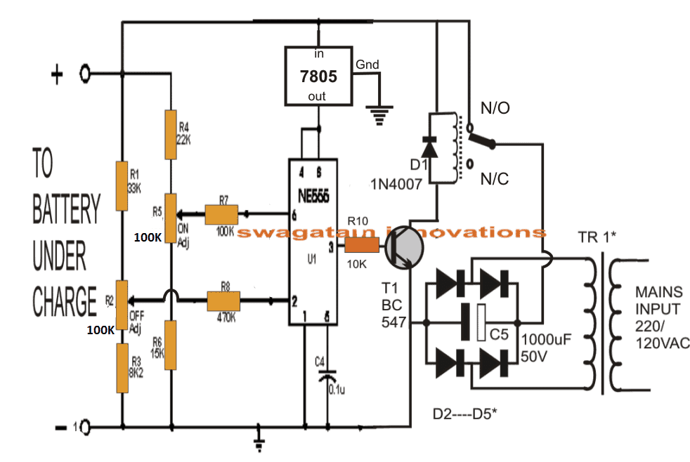
IC 555 Pinouts

IC 7805 Pinout
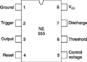
Be aware! An observant blog reader identified what may have been a circuit fault. They speculate that R2 and R5, the setting resistors, could not be accurate. They claim that rather of 10k ohms, the values should be 100k ohms. With 100k resistors, they constructed the circuit and claimed success. We appreciate your insightful comments and will verify the component list again.
The prior diagram has been updated as indicated below based on suggestions from the community. With preset resistors R2 and R5 set to 100k ohms, this is the main modification.
IC 555 Battery Charger with Zero Current Detection Auto Shut-Off
When the charging current drops to zero, signaling a completely charged battery, this IC 555 lead-acid battery charger circuit automatically shuts off. It does this by including a current sensor at pin 2. Below is a view of the full circuit schematic.

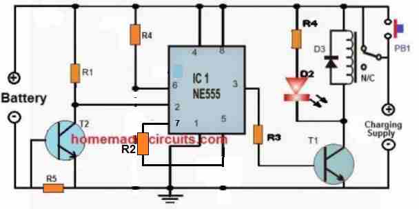
- R1, R3 = 10k
- R2 = 100k
- LED resistor can be 1k
- Pin#6 resistor R4 can be shorted with jumper link
- R5 = 1 / max charging current
- Relay = 12V relay for 12V battery.
- Relay diode = 1N4007
- T1, T2 = BC547
How it Works
By temporarily pressing a button, this circuit may be made to function as a latching circuit, which allows it to be switched on and off. In this mode, it functions as follows:
Beginning State: The relay is attached to the Normally Closed, or N/C, contacts and is off when power is initially provided.
A brief conduit for current to pass via the push button (PB1) and the battery is created when the button is pressed (R5 functions as a current limiter).
Switching on the Latch: With the battery serving as the load, the transistor T2 is turned on by the voltage drop across resistor R5.
Latching ON: Pin 2 of the IC 555 is driven low when T2 is conducting. The relay is activated when this causes pin 3 on the output to go high.
The battery charging circuit is completed when the relay flips its contacts to the Normally Open (N/O) position.
Crucially, T2 simply has to be turned on for PB1 to begin this process; it only needs to be pressed briefly.
Automatic Shut-Off: The voltage drop across R5 progressively drops as the battery charges. T2 stops conducting when the voltage drop across R5 is too small to maintain the battery's near-full charge.
Resetting the latch involves turning off T2, which makes pin 2 of the IC go high once more. Consequently, pin 3 is switched (pin 3 goes low) and the relay is deactivated. As a result, the battery's charging circuit is cut off.
Important Note: To activate the circuit in this latching mode, only pushing the button (PB1) briefly is required. When the battery gets close to being fully charged, the circuit automatically controls the charging process and turns off.