
Impress everyone with your voice-activated LED bow tie! In this post, we'll guide you through building a circuit that makes LEDs on your bow tie blink in response to your voice.
Imagine the LEDs flashing and illuminating your tie whenever you speak – a surefire way to grab attention!

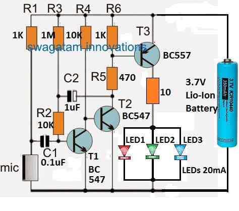
Circuit Diagram

Parts List
- Resistors 1/4 watt CFR unless specified
- 1K = 2
- 10k = 2
- 1M = 1
- 470 Ohms = 1
- 10 Ohms = 1
- Capacitors
- 0.1uF Ceramic = 1
- 1uF/25V Electrolytic = 1
- Transistor BC547 = 2
- Transistor BC557 = 1
- LEDs = Quantity as Required, 20 mA, 5mm type
- Electret MIC = 1
- Battery 3.7 V = 1
How the Circuit Works
This section dives into how the circuit breathes life into your voice-activated bow tie. Let's break it down step by step:
Boosting the Signal (Preamplifier): Resistors R1, R2, R3, and transistor T1 work together like a tiny microphone booster. They take the weak electrical signal from the microphone (MIC) and amplify it into a stronger signal.
Powering the LEDs (Power Amplifier): Transistors T2 and T3, along with resistors R4, R5, and R6, act as a power amplifier. This section takes the amplified signal and further increases its strength to light up the LEDs.
LED Illumination and Delay: When the microphone picks up your voice, the amplified signal reaches the LEDs through transistor T3.
This makes them light up! Resistor R3 and capacitor C2 work together to create a short delay.
Even after you stop speaking, the LEDs will stay on for a brief moment before fading out. You can adjust this delay by changing the value of capacitor C2 (see formula below).
Tip: To save battery life, you can skip the delay feature altogether by removing capacitor C2.
Battery and LED Choices
Power Source: You can use a standard Lithium-ion (Li-ion) AAA battery (3.7V) for your bow tie. If you want a more compact design, consider two 3V Lithium-ion coin cells connected in series.
Battery Life: Since the LEDs only activate with your voice, the circuit uses minimal power when you're not talking, maximizing battery life.
When the battery runs out, you can recharge it using a phone charger with a 6V incandescent bulb or a 50-ohm, 1-watt resistor connected in series (for safety).
LED Customization: Feel free to get creative with your LEDs! Choose different colors (all high brightness, 3.3V, 20mA) to match your style.
You can even connect 3 to 6 LEDs in parallel for a brighter effect (refer to the circuit diagram for reference).
Fine-Tuning the Delay (Optional):
The circuit includes a delay feature that keeps the LEDs lit for a short while after your voice stops. This can be a cool effect, but if you prefer the LEDs to turn off instantly, you can skip this step.
However, if you'd like to adjust the delay time, here's the formula:
t = -RC * ln(1 - VS / VC)
where:
- t = delay time in seconds
- R = resistance of R3 (in ohms) - You'll find this value in the circuit schematic.
- C = capacitance of C2 (in farads) - This value can be adjusted to change the delay.
- VS = supply voltage (usually 3.7V for Li-ion battery)
- VC = voltage across capacitor C2 at which the timer turns off (unknown, but typically a fraction of VS)
Important Note: This formula involves some advanced electrical concepts. If you're not comfortable with them, it's perfectly fine to leave the delay feature out by removing capacitor C2 from the circuit.