
A gsm automobile security system with this really basic circuit design actually functions.Unbelievably so? Discover and absorb how to build it simply. Consider how it would make you feel to be able to operate your car from anywhere in the globe with just your smartphone. Get further information on creating a DIY cellular home security system.
Introduction
I've always wanted to know how to get wealthy by creating a concept that may have a straightforward layout yet revolutionary features.
For the mere reason that these devices can transport signals wirelessly around the world in a matter of seconds despite being so little and elegant in design, cell phones have always piqued my interest.
I had the idea one day: is there a straightforward method to take use of this amazing functionality so that it may be used as a "cell phone remote control" to control any device with a single button push from anywhere in the world?
Given that every commercial GSM-based remote control requires a modem, what prevents a mobile phone from serving as a modem as well?
One may easily obtain, install, and utilize such a "modem" for a reasonable cost. Not only that, but traditional GSM modems are expensive, hard to wire, and require specific SIM cards and advance notice to the network providers in order to work.
After much perseverance and inspiration from the brilliant idea, I was able to complete a very good and reasonably priced gsm car security system that could not only centrally lock and immobilize a vehicle, additionally transmit a revert back call to the owner.
The owner's cell phone makes successive miss calls to arm and disarm the device; no call expenses are paid in the process.
Glowing with the success of the endeavor, I made the decision to get in touch with the right businesses to advertise the unit. But the surprising news was just that—news.
These businesses rejected my device on the grounds that it wasn't designed in a "industrial" manner and that using a mobile phone that was connected as a modem was improper.
really sad Ultimately, I had to abandon the option since it was difficult to market and sell the unit through friends and family because it required a significant upfront cost and ongoing maintenance.
However, there is excellent news for you all: I am prepared to provide all the specifics of this genuinely remarkable circuit and to discuss with you every achievement story.
The circuit is really straightforward, impenetrable, and failsafe—in fact, it has been operating flawlessly as a security door lock in four cars and one jewelry store for the past six months or so.

The Key Elements of the Circuit
There are no call expenses because the car is locked and unlocked through consecutive miss calls. You can do the aforementioned operation from anywhere in the world.
The vehicle's engine may be turned off remotely from anywhere in the globe, even while it is moving. Car When a miss call is rejected and the owner's phone continues to ring, the car has been unlocked. This is known as locked confirmation.
Various phone numbers can be assigned to the program's mobile phone, limiting its ability to respond to and operate solely through these numbers.
Basically, an incursion or a burglary is translated into a warning revert back call to the owner's mobile phone. In the unlikely event that the owner forgets to lock the car, the gadget has an automated locking mechanism built in.
A prepaid SIM card that fits into the modem (connected mobile phone module) is a prerequisite. You will pay just less than 100 bucks USD for the complete unit.
Note: If you install the unit with another security system that has previously been put in your car, it won't function. Next we're going to learn precisely how to construct this GSM vehicle.
The Trigger Circuit

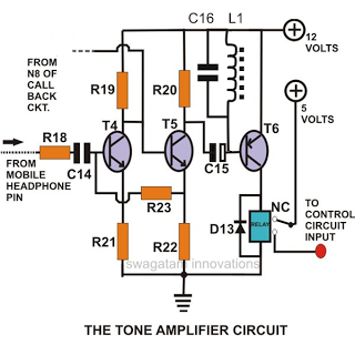
The tiny two transistor circuit, as seen in the circuit schematic, creates a fundamental "beep once" tone amplifier that plugs into the phone's headphone connector.
Since this ring tone is associated with a number of undesired malfunctions or intense radiofrequency disturbances, it turned crucial to prevent them from getting into the primary control circuit.
The whole system might be shaken by these disruptions, leading to strange outcomes. Simply for the rectification mentioned above, resistor R18, capacitor C16, and inductor L1 are all provided.
For as long as the tone continues, the amplified signal enters a relay and briefly energizes it.
The main flip/flop control circuit receives a logic high signal from the relay and it works since the unit's supply voltage is linked across the relay's N/O contacts.
By using a relay, you can be confident that it is only being driven by a real ringtone pulse and not by some other strange accidental interference coming from the mobile phone (if they can even get past R18, C16, and L1 protections).
PARTS LIST
All Resistors are ¼ watt 5% CFR, unless otherwise stated.
| Reference | Value |
|---|---|
| R18 | 100 ohms |
| R19 | 22K |
| R20 | 4K7 |
| R21 | 220 Ohms |
| R22 | 1K |
| R23 | 10K |
| C14 | 2.2μF PPC (PolyPropelene Capacitor) |
| C15 | 47μF/25V |
| C16 | 0.1μF/100V PPC |
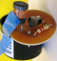
| L1 | 40mH, BUZZER COIL, OR THINNEST POSSIBLE COPPER WIRE WOUND OVER ANY FERRITE MATERIAL WITH 1000 TO 2000TURNS. |
| Relay | 12V/400 Ohms |
| Diode | 1N4007 |
| T4/T5 | BC547 |
| T6 | BC557 |
The reference figure below shows the buzzer inductor clearly. On the other hand, L1 could be obtained from any common piezo buzzer.

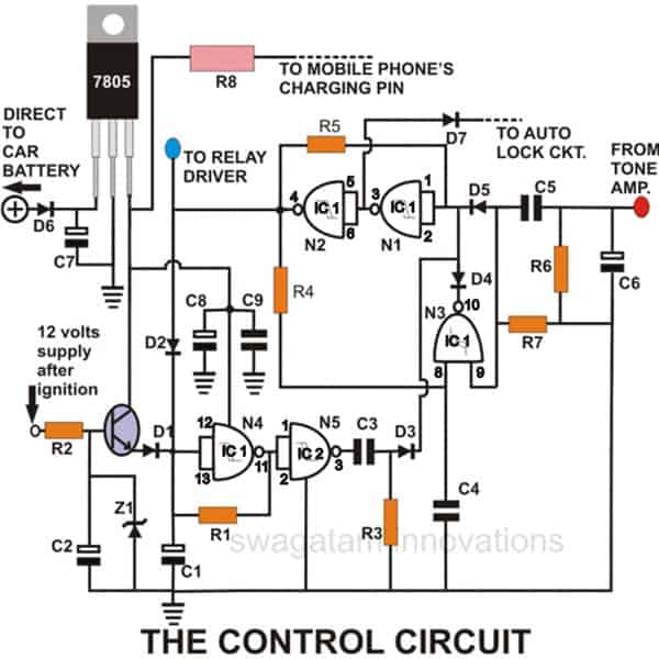
The Primary Circuit for Control
In essence, this circuit is a Flip/Flop circuit which, in anticipation of the input signal from the circuit above, switches to alternatively create a stable logic Hi or a logic Lo.
I'll spare you the gory circuit explanation because I've already covered this specific circuit in one of my earlier posts.
The car's central locking and ignition systems are turned on and off using this circuit's output.
PARTS LIST
| Reference | Value |
|---|---|
| R1 | 1M |
| R7 | 1M |
| R2 | 10K |
| R3 | 39K |
| R4 | 2M2 |
| R5 | 2M2 |
| R6 | 10K |
| R8 | 22E(2W) |
| C1 | 100uF/25V |
| C2 | 10uF/25V |
| C9 | 0.1PPC |
| C3 | 0.22PPC |
| C4 | 0.22PPC |
| C5 | 0.22PPC |
| C6 | 33uF/25V |
| C7 | 33uF/25V |
| C8 | 33uF/25V |
| All Diodes | 1N4148 |
| T1 | BC547 |
| Zener | 4.7V/400mW |
| IC1 | 4093 |
| IC2 | 4093 |
The Automatic Lock Mechanism
This gsm vehicle security system's auto lock feature may be explained in the following manner:
As seen in the picture, the auto lock consisting of N4 and N5 is rendered inoperative and inoperative for as long as the output of N2 remains high, indicating that the system is locked.
When N2's output toggles low, N4 begins to count. Following a certain amount of time (based on R1 and C1), N5's output goes high, triggering a trigger pulse at N1's input that toggles N2 back to the locked configuration and disables the auto lock once more.
It is therefore impossible to leave the system unlocked for longer than the predetermined amount of time. To prevent the auto lock from starting inside this predetermined window of time, the car owner must place the ignition key in the designated slot.
The ignition key will stop working after the car is locked until the owner uses their cell phone to unlock the system.

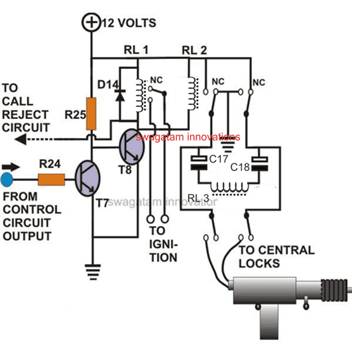
The Central Locking Circuit and the Ignition Control Circuit
R24, T7, and T8 make up what is essentially a straightforward relay driver circuit, as seen in the figure. T7 and T8 respond to the pulse received from the aforementioned circuit by turning on and off the ignition relay contacts in turn.
In order for the ignition system and the central locking relay set to operate simultaneously, T1 is also configured. The vehicle's (the car's) doors are locked and unlocked by the central locking action.
Car doors often have a central locking mechanism that consists of a DC motor that is driven by successive pulses of positive and negative instantaneous voltage to lock (pull) and unlock (push) the door lever.
The current sets of relays and capacitors were configured to produce the aforesaid performance while taking this specific characteristic into consideration.
PARTS LIST
- All Resistors are ¼ watt 5% CFR, unless otherwise stated.
| Reference | Value |
|---|---|
| R24 | 15K |
| R25 | 4K7 |
| C18 | 470uF/25V |
| C17 | 470uF/25V |
| T7 | BC547 |
| T8 | D1351 |
| D14 | 1N4007 |
| RL1 | 12V/100 Ohms/10Amps. |
| RL2 | 12V/100 Ohms/10Amps. DPDT |
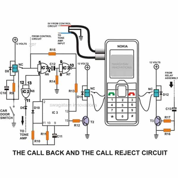
The Call Back Feature
We can observe from the circuit diagram that the IC 4060 is configured in the default oscillator mode. The vehicle's door switch is mechanically attached to the relay coil (extreme left). A monostable made up of N6 and N7 is triggered while the door is in its locked position because the system interprets any opening as a "intrusion" that briefly activates the relay.
The output of N7 therefore immediately drops, resetting pin # 12 of IC 4060 and initiating a countdown. Following several seconds, pin #2 of the IC gets high and locks on its own, but at this specific time, pin #15 of the IC generates precisely four pulses and is utilized to drive a relay whose contacts are linked to the call button.
As a result, the mobile phone begins ringing, alerting the owner to a potential theft or break-in right away.
After precisely one and a half minutes, monostable N6 and N7 will free themselves. During this time, the circuit is "sealed" and won't react to anything, not even missed calls from the owner's cell phone.
In order to prevent the circuit from being disrupted when the connected cell phone (Modem) tries to call the owner, this function has been specifically included.
PARTS LIST
| Reference | Value |
|---|---|
| R9 | 10K |
| R10 | 2M2 |
| R11 | 330K |
| R12 | 4K7 |
| R13 | 39K |
| R14 | 1M |
| R15 | 1K |
| R16 | 330E |
| R17 | 1K |
| C10 | 100uF/25V |
| C12 | 100uF/25V |
| C11 | 0.001uFDISC |
| C13 | 47uF/25V |
| D9 | 1N4148 |
| D10 | 1N4148 |
| D8 | 1N4007 |
| D11 | 1N4007 |
| D12 | 1N4007 |
| T2 | BC547 |
| T3 | BC547 |
| IC2 (N6,N7,N8) | 4093 |
| IC3 | 4069 |
| Relays | 12V/400 Ohms |
All Resistors are ¼ watt 5% CFR, unless otherwise stated.
The Call Rejection Feature
As seen in the above diagram, an additional relay driver circuit handles the "call rejection" feature.
A pulse is delivered to the driver transistor's base, which temporarily turns on a relay, when the system is locked by the owner's miss call.
The owner's phone call is now promptly denied and a "network busy" message appears on the phone, verifying that the car is safely secured, because the contacts of the relay have been wired across the "cancel" button of the connected mobile phone (Modem).
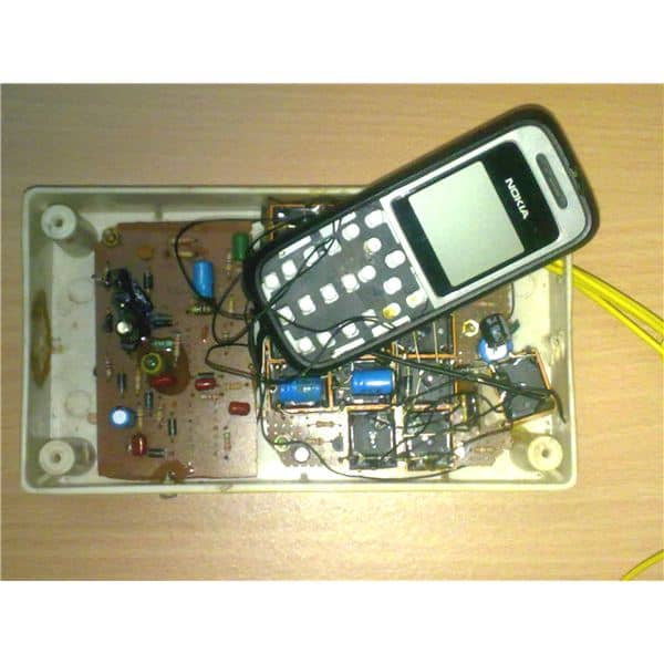
How to Interface with the Modem Cell Phone Internally
This cellular vehicle security system's modem's internal wiring may be comprehended as follows: This wiring portion will require extreme caution; if you are not skilled sufficiently, stuff might become quite messy and ruin the entire "game."
The following tasks might be best accomplished with the assistance of a mobile phone engineers:
Needless to mention, the exterior layer and the metal mesh within the phone that protects the keypads should be discarded.
Remove the keypad label very delicately and slowly, then store it in a safe location for future use.
The integrated keypads are visible to the naked eye. Unfortunately, these pads can't be soldered, consequently external wires from the appropriate relay contacts can't be connected to them.
The only option left is to attach the necessary wires to the keypads by putting their bare extremities there, and then allow the metal mesh frame and keypad sticker take care of the rest by pushing the wires tightly into the keypads to establish a trustworthy connection.
A 36 SWG super enameled wire should work pretty well, or you could employ the thin, insulated wires that are usually used to wire piezo transducers.
Remember to "tin" the exposed wire terminals to ensure proper contact with the keypads.
Additionally, don't forget to take out the tiny metal contacts in the shape of discs from the sticker at the locations where the call and cancel buttons are located. Once this is done, you could gently put the sticker back in place to securely protect the linked wires in their designated locations.
To finish the "modem" construction, proceed to secure the metal wire web and tighten it strongly. It is not necessary to change the topmost acrylic covering, so please don't attempt. After the entire circuit construction is finished, this modem installation is now prepared and may be linked to the main circuit.
The Charger Section
This GSM auto security system's charger part makes use of a current controlling resistor and regulator IC 7805. For the purpose of gradually charging the battery of the cell phone modem, it is always attached to it.
Given that every Nokia phone includes an integrated autonomous smart cut-off circuit, there is no risk of overcharging the battery.
Configuring the Cell Phone Modem Attachment
The aforementioned mobile phone modem may be configured by carrying out these simple instructions once the whole circuit assembly and all connections are finished: Take out the pre-paid SIM card from the Modem and use a piece of conductor to short circuit the phone's exterior "cancel button" wires to turn it on. It can only be turned on in this manner because keypads are no longer in use.
Keep the cell phone numbers that would be used to run the device. Navigate to the "name" section of each of the previously saved numbers, then choose "No Tone" under Assign Tone under Options. Go to settings, then tone settings, then choose empty to turn off the typical ringtone.
Configure the message's tone the same way, leaving it in the OFF position. Additionally, turn off the initialization, notification, and keypad sounds by choosing the appropriate instructions.
Whenever an unauthorized use is detected, the modem will consequently "understand" precisely how to call back and will consistently call you back on this specific number each time the car door unlocks (simply because the security system is in locked position). To finish, make a call from this modem cell phone into your cell phone through shorting out its call button three times by connecting an element of conductor. The modem is currently operational and fully configured.
How to Test the Unit?
Following the completion of the comprehensive construction process outlined in the writing, you can validate this exceptional gsm automobile security system using these easy steps:
The mobile phone modem should display "Charging" as soon as you connect a high-quality, 12 volt regulated power source to the circuit, meaning that the method of charging has started and is operating flawlessly.
Attach a tiny 12-volt motor to the circuit's "central lock" outputs. When you first dial the SIM card number, the relays begin functioning as soon as your call reaches the mobile phone modem. The attached motor will then alternatively invert its direction of revolution for each call that follows.
This verifies that the complete circuit, including the central lock component, is functioning flawlessly.
Using a DMM, verify that the igniting portion is continuous. Every time you make a call after that, it ought to make and break. Corresponding to this, you might confirm the appropriate part by connecting a siren-style horn to the alarm output.
After a brief sounds, the alarm should go off for each call the modem receives. Ground C10/R9's common point when the ignition relays are locked (deactivated), since this might occur if the automobile door is unlocked (intrusion). The callback feature is operational; the modem must begin phoning the saved number right away, and you'll get a call on your mobile phone.
After following the above instructions, you must be able to verify that the system is operating correctly and be ready to fix it in your automobile and see the incredible accomplishments yourself.