
Transformers are a common component of traditional power supplies, however they may be large and heavy for low-power uses. A more compact design is provided by transformerless designs. However, the possibility of a spike in current at turn-on is a significant worry with transformerless circuits.
The zero-crossing transformerless power supply is a creative approach that is presented in this article. These circuits use zero-crossing detection to minimize the initial current flow and reduce surge current by only turning on when the AC voltage is exactly zero. This considerably lowers the possibility of breaking your circuit.
We'll be looking at a few transformerless zero-crossing circuit designs. These designs prioritize surge protection with zero-crossing detection and also offers a possibly smaller and less expensive solution. We'll examine this circuit's operation and advantages.
1) Zero Crossing Transformerless Power Supply Circuit
Our first circuit demonstrates how important zero crossing detection is to protecting capacitive transformerless power supply against inrush current spikes during mains power-up. It was Mr. Frank who presented this idea.
Here's the technical specifications proposed by Mr. Frank
Required Specifications
Reading your writings about transformerless power sources has been fascinating. Even though I'm not very good with electronics, I know that the main problem is the inrush current spike that happens when a device is turned on before it reaches the zero voltage point, or zero crossover. Is it possible for zero crossing detection to fix this problem?
Given the minimal power needs of the optotriac's input, voltage reduction may be achieved with just a basic resistor, obviating the need for a capacitor at the input.
The DC circuit would then be powered by the output-side capacitor, which would be turned on by the zero-crossing triac.
If practical, this method might allow for the control of greater current/voltage loads with the triac while also resolving the issue of inrush current. Could you provide any real-world examples of this idea?
The Design
As the aforementioned idea correctly notes, one of the main reasons for a surge current inrush in capacitive transformerless power supply might be an AC input without a zero crossing regulation.

Zero-Crossing Control Is Made Simpler by Modern Triac Drivers
Current developments in opto-isolators for triac drivers have greatly streamlined the process of switching AC mains with zero-crossing control. Zero-crossing detection and control of these specialist devices, called MOCxxx optocouplers, makes it simple to combine them with any triac for the management of AC power.
The MOC Series: Experts in Zero-Crossing
The optocouplers of the MOC series of triac drivers are made especially for zero-crossing control. With minor differences in voltage parameters, these devices (MOC3041, MOC3042, MOC3043, etc.) give almost equal performance. With capacitive power supply, surge management is possible with any of these devices.
Internal Management of Zero-Crossing
The detection and execution of zero-crossing are handled internally by these optocouplers. To get the necessary zero-crossing regulated firing of the integrated triac circuit, users only need to setup the power triac with the selected MOC device.
Recognizing Zero Crossing Before Proceeding
Let's first examine the idea of zero crossing and its associated properties before looking at the zero-crossing control circuit for a surge-free triac transformerless power supply.
Comprehending AC Power Zero Crossing
The type of electricity that comes from a wall outlet, or AC power, is always altering. It starts at zero volts, increases to a peak voltage (about 310 volts for a 220V system), decreases to a negative peak voltage, and then decreases to zero once again. This cycle has 50 repetitions per second, or 50 Hz.
Zero crossing is an important concept to comprehend. This is the point at which the voltage changes from positive to negative, exactly zero volts.
The Significance of Zero Crossing in Capacitive Power Supply
When first turned on, capacitive power supply may be sensitive. The power supply and any attached devices may sustain damage if they are turned on at a peak voltage, as the whole force of the AC current may burst through them.
This occurs because, when initially connected to a power source, capacitors behave briefly like a short circuit. After that, they instantly charge and start functioning properly.
Zero Crossing: A Lifesaver!
The good news is that there won't be much current flow if you turn on a capacitive power source at a zero crossing point, which occurs when the voltage is zero. This lowers the possibility of a destructive spike considerably.
You can make sure your capacitive power supply goes on securely and without any inrush current by utilizing a circuit that detects zero crossings.
Circuit Description
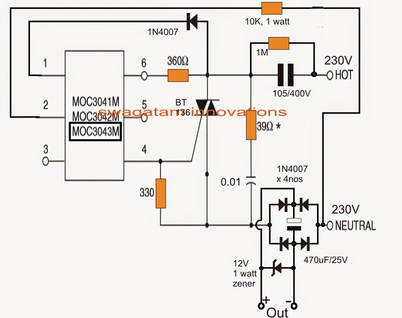
An unique chip used in the circuit is a MOC3041 triac driver optoisolator. This chip makes sure that if you turn on the power, the linked triac only activates during the first zero crossing of the AC power cycle. The AC power remains on normally after that first turn-on until you turn it off again.
Examine the diagram, assuming that one exists. The little 6-pin MOC3041 chip will be visible attached to a triac. They collaborate in this way.
The AC power is sent to the triac via a specific capacitor (105V, 400V rated) that restricts the current. For your load, which in this case may be an LED, a bridge rectifier is utilized on the other side of the power supply to convert the AC into pure DC.
How Zero-Crossing Works to Stop the Surge
The triac remains off when you initially switch on the power since it isn't receiving a signal to turn on. This implies that the load that is linked to the bridge rectifier remains off as well.
The circuit avoids a surge in this way:
A tiny quantity of AC electricity passes via a unique capacitor (rated at 400V, 105V) and arrives at a light detector located inside the MOC chip (pins 1 and 2), waiting for the ideal time.
Zero crossing detection: This AC signal is continuously observed by the MOC chip. The chip senses the zero crossing point, which is reached by the AC voltage, and activates an internal switch.
Safe turn-on: The triac is turned on by a signal from the internal switch. This makes it possible for AC power to reach the bridge rectifier and, eventually, your load (such as an LED).
With this configuration, the triac will only activate during the AC cycle's zero crossing point. This reduces the current spike that occurs when the power initially comes on, safeguarding your load from harm.
Improved Capacitive Power Supply Circuit with Zero Crossing Detection
The following idea discusses a complete circuit for a capacitive power supply that includes a voltage regulator, surge suppressor, and zero crossing detector.
Mr. Cams proposed the concept.
I'm going to provide my idea for a voltage-regulated, zero-crossing detecting, surge-protecting capacitive power supply. I would like your opinion on the following points:
Circuit Synopsis:
Voltage control, surge suppression, and zero crossing detection are all included in this testing-only circuit. I am aware that the choice of capacitor may be pricey, but this is only for testing.

Concerns and Suggestions:
Triac Selection: In order to handle greater currents, should I use a BTA06 triac or a BT136 triac?
The maximum voltage for the Q1 (TIP31C) at this time is 100V. Is the 2SC4381, a 200V, 2-3A transistor, a better option?
For R6, I had accidentally used a 200Ω 5W resistor. A 1kΩ resistor is what it should be. Is the 200Ω resistor functional in this scenario?
We changed a few resistors to operate at 110V according to your suggestions. Does a lower value for the 10kΩ resistor make sense?
Working Together and Sharing:
Based on your comments, I'd be pleased to make any required modifications. If everything works OK, I may design a PCB layout for possible online posting on your website (at no cost to you).
Examination of Circuits
Your circuit design seems to work well overall. My responses to your particular queries are as follows:
You're correct, a better current-handling triac should be used in place of the BT136.
It's a good idea to swap out the TIP31C for a 200V Darlington transistor, such as the BU-806. This will guarantee correct functionality.
You can raise the value of the base resistor since you are using a Darlington transistor. A 2-watt, 1kΩ resistor would work well.
I hope this is useful. Please contact me with any more queries.
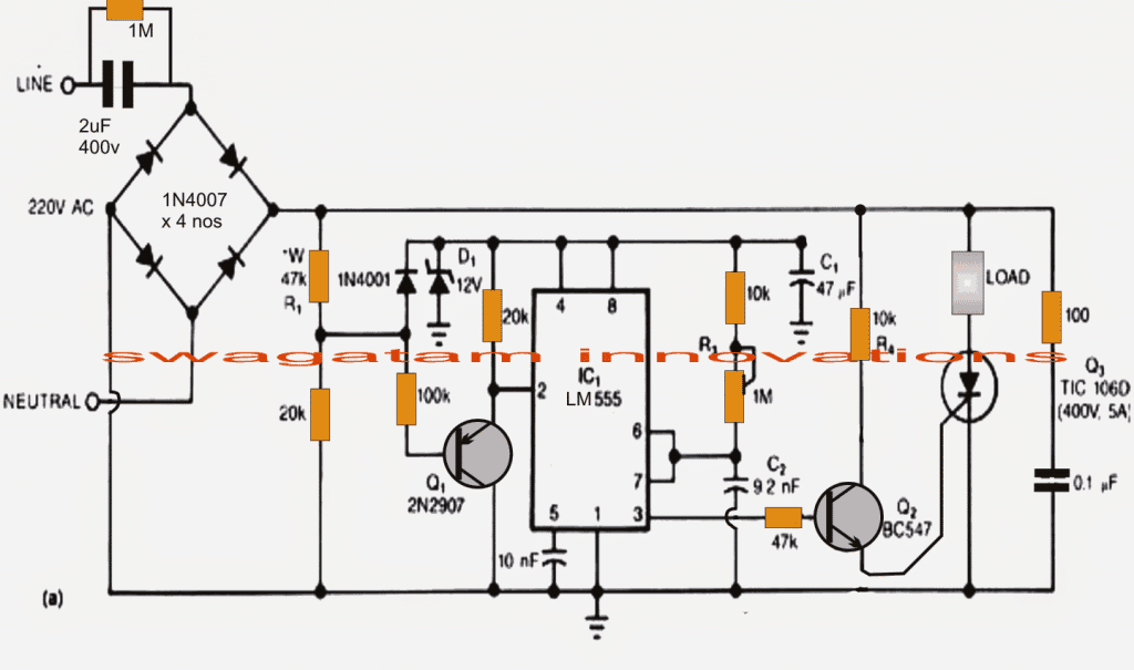
2) Zero-Crossing Controlled Transformerless Power Supply with 555 Timer
This innovative method deals with inrush current in a transformerless power supply by using a 555 timer in monostable mode.
The design restricts the entry of mains electricity to times when the AC signal is zero crossing by integrating a zero-crossing detecting circuit.
This effectively removes the possibility of inrush surge damage. One of this blog's devoted readers suggested the idea.
Transformerless Circuit with Zero Crossing for Inrush Current
By just turning on at the 0 point of the 50/60 Hz cycle, would a zero-crossing transformerless circuit eliminate the initial inrush current?
Yes, a transformerless power supply's inrush current may be greatly decreased by using a zero-crossing circuit. This functionality is built-in to many solid-state relays that are inexpensive (less than INR 10.00).
Choosing the Right Capacitor and Dissipating Heat for a 20W LED Driver
Questions: I want to drive 20W LEDs using this setup. The temperature of the capacitor and the current are unknown to me.
What effects does series versus parallel LED wiring have on the temperature of the capacitor and current?
When a 125uF, 5 amp capacitor overheats, will it fail?
How can I read a capacitor's datasheet to find out how much energy it can dissipate?
IC 555-Based Zero-Crossing Circuit
After looking into fixes for the inrush current problem, I discovered a great transformerless power supply circuit that used zero-crossing switching with a 555 timer. It appears that this design effectively reduces the possibility of inrush surges.
Recognizing Zero Crossing to Create Safer Circuits
Let's examine the idea of zero crossing first before delving into the surge-free transformerless circuit.
The oscillating current waveform (AC)
Think of your wall outlet's AC electricity as a wave. A sine wave is a wave that oscillates continuously in both directions. Starting at zero volts, it progressively increases to a peak voltage (often between 120 and 220 volts, depending on your area), and then it progressively decreases down to zero.
Once the wave reaches zero, it dives below zero and continues in the same negative direction until it reaches zero once more. This cycle repeats either 50 or 60 times per second, based on the electrical requirements in your area.
It might be dangerous to switch on a circuit at any voltage other than zero volts since this wave is continuously changing. A surge may result from the high current flowing at the wave's peak or trough, which might harm your circuit.
The good thing is that there will be very little current flow if you switch on a circuit at the precise instant when the voltage is zero (also known as the zero crossing point). This lowers the possibility of a destructive spike considerably.
You may guarantee that your circuit switches on securely and without any inrush current by utilizing a circuit that detects zero crossings. The suggested circuit makes use of this idea of zero crossing to produce a transformerless power supply that is free from surges.
The Circuit's Operation (see the diagram below):
A bridge rectifier made up of four 1N4007 diodes transforms the AC mains power into a pulsating DC voltage. Even at 100 Hz, double the frequency of the AC line, there are ripples in this DC voltage.
Ripple smoothing:
The voltage level is lowered by a voltage divider created by the 20k and 47k resistors. Subsequently, diode D1 and capacitor C1 filter this voltage to eliminate the majority of the residual 100Hz ripple. Transistor Q1's base receives a part of this filtered voltage via a 100k resistor.
Determining Zero Crossing:
The configuration of the IC 555 is that of a monostable multivibrator (MMV). This indicates that its pin 2 (trigger) will only get high in response to a trigger signal forcing it to ground.
Activation at the Zero Crossing:
Transistor Q1 stays off when the AC voltage exceeds +0.6V, a little threshold that the circuit has set.
Q1 activates when the AC waveform hits zero, or just under +0.6V. As a result, pin 2 of the IC is grounded, and pin 3 produces a positive output.
Providing power to the load:
The SCR (silicon controlled rectifier), which provides power to your load (an LED in this example), is activated by the IC output. This keeps on until the 1M potentiometer's timer expires.
Modifiable Illumination
The timer's on-time may be adjusted by varying the 1M potentiometer. An extended on-time provides the LED with additional current, increasing its brightness.
Protection Against Surges:
Most notably, this circuit only activates the SCR in the vicinity of the AC waveform's zero crossing point. By reducing the surge current during the circuit's first power-on, this safeguards your load from harm.
Circuit Diagram

3) Simple 220V to 50V Converter Circuit without a Transformer
A full-wave rectified DC voltage, about 300 volts, is produced by the bridge rectifier, BR1, from the AC voltage of PL1. The resistors R1 and R2, diodes D1, D3, and D4, and the network they form provide a sequence of 5-volt pulses that are essential for two reasons:

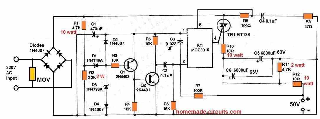
A sequence of 5-volt pulses is produced by the network of resistors (R1, R2) and diodes (D1, D3, D4), which has two crucial functions:
A portion of the pulses are used by capacitor C1 and diode D2 to form the pulses and produce a steady 5-volt power source for the timer circuit.
The remaining pulses turn on a number of parts that regulate the output voltage, including:
Circuit for timer (C2, R6), pulse shaping circuit (Q1, Q2, R3–R5), power triac (TR1), and optoisolator (1C1).
Resistor R2 regulates the maximum pulse width in addition to the output peak voltage. If there was no feedback network, the output can be as high as 90 volts.
A feedback loop is formed by capacitor C3, resistors R6, and R7. This loop essentially turns off the optoisolator by sending a signal to it whenever the output voltage increases over 50 volts.
As a result, the triac (TR1) loses power, which lowers the unregulated voltage and causes the triac to trip. The output voltage is maintained at around 50 volts thanks to this feedback system.
By limiting the current passing through the optoisolator, resistor R8 maintains the stability of the device.
Additional components that support the optoisolator's steady operation include resistor R9 and capacitor C4.
To safeguard the triac, resistor R10 restricts the surge current when the circuit is first turned on.
A low-pass filter (R10, C5, C6) minimizes any residual output voltage ripple.
Capacitors C5 and C6 are discharged when the power is turned off via resistor R11.
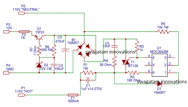
4) Recommended: Cheap and Safe Transformerless Power Supply
Mr. Swagatam developed the circuit design below while looking for a low-cost, transformerless power supply with 0% crossover. Although simulations show promise, real-world testing is necessary to confirm its functionality.
Below is the whole circuit schematic. Any comments or recommendations from the community would be greatly appreciated, particularly with reference to possible areas for testing and optimization.

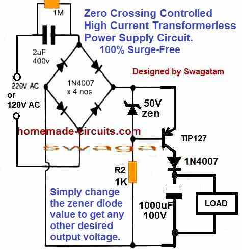
In order to create a more controllable and secure power source, this circuit design integrates voltage regulation and zero-crossing detection. This is how it operates:
AC Input Reduction: Before the AC current reaches the bridge rectifier, it is limited by the 2uF capacitor to around 200mA.
Next, the lowered AC voltage—which is still around 220V—is transformed by the bridge rectifier into a pulsing DC voltage—which is roughly 310V.
Zero-Crossing Detection and Control: A voltage reference is provided by the 50V zener diode.
The transistor is reverse-biased (non-conducting) by the 1k resistor and the zener diode stays off when the DC voltage from the bridge rectifier exceeds 50V (peak voltage). Any high voltage spikes throughout the AC cycle are effectively blocked by this.
Nevertheless, the zener diode conducts during zero crossing, when the AC waveform falls below 50V, causing the transistor to become forward-biased.
Safe Power Delivery: The circuit permits a specific amount of current to flow when the transistor is conducting, charging the 1000uF capacitor to about 50V.
The load is then given this controlled 50V DC voltage from the capacitor, guaranteeing steady and secure functioning.
Selecting a Transistor: The transistor that is now on display may have a voltage rating of 100V, which is too low for the circuit.
If this worries you, think about switching it out with a transistor with a greater voltage rating (400V), such as the MJE5852.
Transformerless Power Supply Advantages
Power supply with transformers are commonly used to convert AC power to DC electricity. Transformers, however, may be large and restrict how compact a circuit can be, particularly when working with modest power needs.
When low DC current (usually less than 100mA) is required for an application, transformerless power sources provide a strong option. They accomplish this by:
Small Dimensions: By doing away with the necessity of a large transformer, the entire circuit design becomes lighter and smaller.
Lower Cost: Eliminating the transformer from the design makes it simpler and may save production costs.
This particular circuit steps down the mains voltage by using a high-voltage capacitor at the input. The lower AC voltage is then converted to a DC output using a bridge rectifier. This design may be used as a straightforward 12V DC power supply for a variety of electrical circuits, as the diagram illustrates.
But it's crucial to recognize that transformerless power supply have certain drawbacks as well.
Disadvantages of Transformerless Power Supply
Although transformerless power sources have advantages in terms of cost and space, it's crucial to take into account their limitations:
Restricted Current Output:
These circuits are usually not appropriate for uses where a significant output current (usually greater than 100mA) is needed. For many low-power electrical gadgets, this shouldn't be a problem.
Minimal Isolation
The lack of separation from the mains voltage is a significant disadvantage. Circuits with exposed parts (such as metal enclosures) or user-accessible outputs may be at danger from this.
Working with transformerless circuits requires caution if you're a novice in order to prevent potential electrical risks.
Ensuring user safety should be the first priority when designing devices. This may be achieved by utilizing shielded enclosures or isolated DC-DC converters.
Availability to Increases:
Transformerless circuits occasionally permit voltage spikes from the AC mains to flow through, which might harm the powered item as well as the circuit.
Protection Against Surges in the Proposed Circuit:
The particular circuit that you shown makes an effort to alleviate this issue by adding voltage stabilization steps following the bridge rectifier. These steps, which most likely involve capacitors, can assist in absorbing brief voltage spikes to safeguard the linked devices.
Warning: High Voltage May Be Fatal!
Due to their lack of isolation between the DC output and the AC mains voltage, transformerless power supply circuits pose a serious danger of electrical shock. It can therefore be linked to the possibly fatally high voltage of the AC mains, even though the output voltage appears modest (e.g., 12V DC).
Safety Measures:
Only Build for Experienced Users: It is advised that only seasoned users who have a firm grasp of electrical safety procedures construct and operate a transformerless power supply.
Not for Applications by Users: Because of the possible shock hazard, these circuits are not recommended for powering user gadgets. For situations where users may come into touch with the circuit or its output, choose isolated power supply.
Appropriate Enclosure: To avoid unintentionally coming into touch with live components, make sure any transformerless power supply you create is contained in a totally sealed, non-conductive enclosure.
Use suitable safety equipment, like as gloves and tools with the right rating, if handling or troubleshooting a transformerless circuit.
Examine Your Options: Use separated power supply, such as isolated DC-DC converters or wall adapters that are sold commercially, for user safety and wider application compatibility.
Recall that electrical safety is very important.
It's advisable to stay on the side of caution and select a safer option if you have any doubts about any part of creating or utilizing a transformerless power source.