
With a compact control device, home automation, sometimes referred to as domotics, enables us to turn on and off a variety of items, including entrance gates, shutters, curtains, TVs, hi-fi systems, and LED lights.
Usually, infrared frequencies—which are invisible to the human eye—are used to send the signals that operate these gadgets. Exact and trustworthy instructions are guaranteed by an advanced coding mechanism.
This data is often transmitted using the RCS code, which has a carrier frequency of 36 kHz and a word with a that includes 14 bits.
Using a TV Remote Control
Given the variety of TV remote controls that are often available in homes, such signals may be used to turn on an additional receiver that reacts only to infrared light that is picked up by something that has an infrared sensor attached to it.
The signal generated by any remote control key may be detected by an easy-to-use, low-cost integrated component for so long as the device's carrier frequency matches the signal.
It doesn't matter what code comes in; in our configuration, a bistable flip-flop operates a power stage which can be a solid state or a relay-based switch.
Thus, building an infrared (I.R.) receiver will soon offer a dependable and affordable remote control solution.
Circuit Description
Security or a code to choose from a variety of instructions are not taken into account here.
Since it's possible to unintentionally trigger your television or VCR remote control, it is obvious that the implementation's goal shouldn't interfere with how they normally function.
Other than this limitation, anything is possible because the responsiveness of the receiver module permits a range that is several hundred meters.
The illustration below displays the entire schematic.

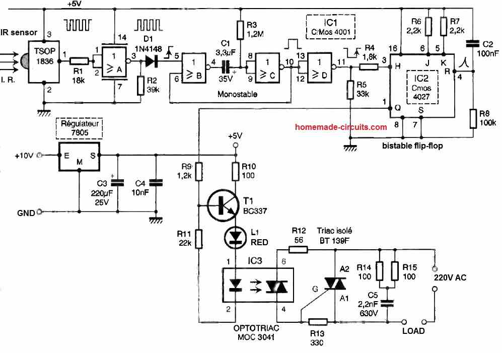
Made up of a preamplifier and a PIN diode, the photosensitive sensor is essentially an embedded infrared receiving device. It also has a bandpass filter, a demodulator, and automatic gain control.
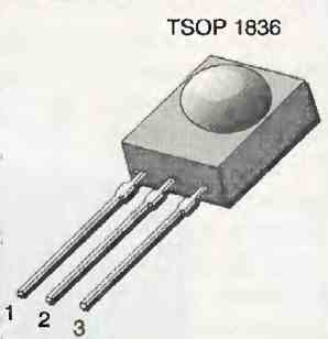
Our selection is the TSOP1836 type from TEMIC, which has a 36 kHz operating frequency and is packaged in a particular three-pin configuration.

We have incorporated filtering capacitors and a 7805 regulator because this sensor needs a 5V power source.
Any key on a regular remote control that is pressed will cause a negative-coded pulse to appear on pin 1 of the sensor.
As we are only concerned with the initial negative edge, it is not required to interpret the signal.
The NOR gate A inverts the signal, which is subsequently delivered to the control input of a monostable flip-flop formed by NOR gates B and C via diode D1.
To prevent any more commands or lengthy presses on the remote control button, a few seconds of pulse width are produced by the positive pulse at the trigger input.
We postpone the point at which the distinct rising edge of the signal might ultimately activate the input of a bistable flip-flop by adding an extra NOR gate to act as an inverter.
We employ the well-known CMOS 4027 circuit, a twin JK flip-flop in master-slave mode, as predicted.
Each input pulse produces consistent output behavior by wiring IC2's J and K inputs to a high level via resistors R6 and R7. This behavior is comparable to that of a well-known lamp timer switch.
The Q output is reset to 0 by one pulse, then changed to 1 by another.
Notably, pin 1 is initialized to a low level at power-up due to the short positive pulse produced by resistor R8 and capacitor C2 combined.
The only thing left to do is make use of IC2's output. At this stage, the transistor T1 may be used to turn on a tiny relay. We tend to choose an entirely constant power output.
A red LED, L1, has been incorporated inside a tiny optoisolator, such MOC 3021 or better still, 3041, that has zero-crossing detection built in.
The triac is safe to use for managing hundreds of watts at 230V without the need for a heat sink.
Construction
On the printed circuit board, there is a rather thick pattern of copper interconnections. Initially three jumpers with naked wires are introduced.

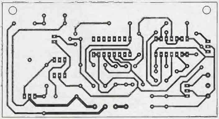

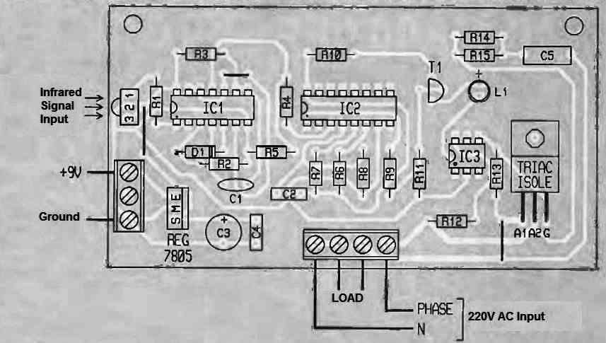
To install the integrated circuits, we suggest utilizing a superior-quality socket, ideally tulip pins.
This arrangement should be protected by having it placed in an appropriate enclosure that allows sufficient room for the 9V tiny battery that powers the shaping and detecting components.
When the IR sensor is installed, its receptive side has to be facing the infrared light which is directed to it.
It is possible to decrease the value of the electrolytic capacitor C1 if it appears that the reaction time between the input pulse and the red LED lighting is becoming excessively prolonged, though not lower than 680 nF.