
Although the majority of battery chargers use voltage detection to initiate automatic shut-off, current sensing is a more accurate technique. Upon the battery reaching its optimal full condition, this method disconnects the power. A circuit using current sensing for automated shut-off is shown in the diagram below.

Circuit Working
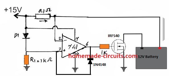
Our current sensor is the tiny 0.1 ohm resistor. During charging, a voltage differential, or potential difference, forms across the resistor as current passes through it. The current is proportionate to this difference.

Choosing the Cutoff Point:
Before the battery can be considered completely charged, it is crucial that this voltage differential reach a certain threshold. The voltage drop across a diode connected to pin 3 of the control chip (IC) is the lowest level that is selected to be 0.3V higher. To put it another way, until the battery is fully charged, the voltage at pin 2 of the IC must be at least 0.3V lower than pin 3.
Connecting and Unplugging:
Charging: A voltage differential, say -1V, is created at the input pins of the integrated circuit (IC) due to the current passing through the resistor as the battery charges.
As a result, pin 2's voltage is at least 0.3V lower than pin 3's.
Consequently, a MOSFET switch receives a signal that activates it and permits current to flow to the battery.
Full Charge and Shut-Off: The battery's current demand reduces as it approaches its full charge level.
As a result, there is almost no voltage differential across the resistor. The voltage at pin 2 now exceeds the voltage at pin 3 as a result of this modification. This change causes the MOSFET switch to be turned off by the IC, removing the battery's connection to the power supply.
The IC's diode that is connected between pins 3 and 6 functions as a latch. Even in the event of a brief power outage, the diode maintains the circuit in this off condition after the battery is detached owing to full charge.
The circuit resets and becomes ready for a fresh charging cycle when the power is completely turned off and then turned back on.
You may also make the following modifications to the aforementioned current-dependent charging circuit.
Power Up and Connection:
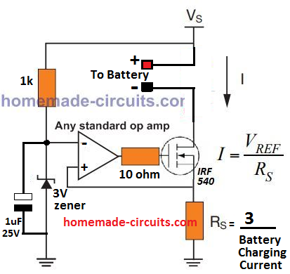
A 1 uF capacitor is used to momentarily link the op-amp's negative input, or inverting pin, to ground when power is turned on. This causes the op-amp's output to momentarily experience a high output.
This initial high output from the op-amp activates a switch known as a MOSFET.
When the MOSFET is turned on, the current sensor resistor (RS) connects the battery to the power source.
Monitoring Current and Charging:
A voltage differential proportionate to the current flows through the resistor (RS) while the battery charges.
The op-amp compares this voltage differential. The op-amp output remains high as long as the voltage across RS is greater than a reference voltage (3V) set at the negative input (inverting pin).
The MOSFET is kept on by the high output of the op-amp, which permits the battery to charge more.
Getting to 100% Charge and Turning Off:
The current drain reduces as the battery gets closer to being fully charged. As a result, the resistor's (RS) voltage differential is less than the 3V reference.
The output of the op-amp flips to low when the voltage across RS is less than the reference.
The MOSFET is turned off by the op-amp's low output, which also disconnects the battery from the power source and halts the charging process.
High Current Charging
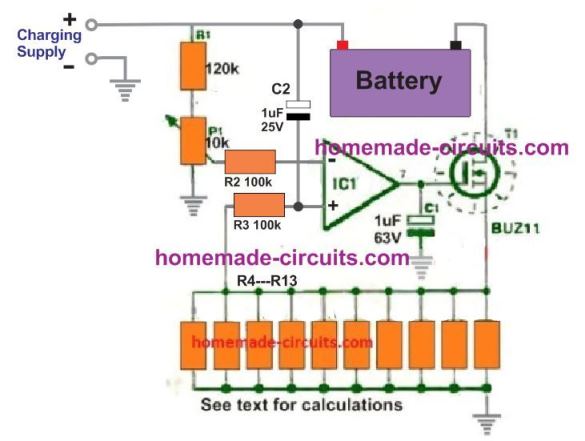
A thorough overview of this current-dependent battery charging method is given in the following diagram. High capacity battery (200 Ah to 500 Ah) charging is very safe with this configuration.

How to Adjust the Current Sensor:
Tweak the 10k Preset: To fine-tune the voltage at the op-amp's inverting input (negative input), use the 10k ohm trimmer resistor (preset). Target a voltage of between 0.3 and 0.4 volts. To measure this voltage, a voltmeter is required.
Configure the Current Sense Resistor: R4 through R13 function as a single current sense resistor when combined. You may alter the overall resistance by varying these resistors. The ideal overall resistance should be:
Total Resistance (R) = 1 / Maximum Charging Current
For example, if your intended maximum charging current is 10 amps and you have a 100 Ah battery, then:
R = 1 / 10 amps = 0.1 ohms
How to Apply the Calculated Resistance
Option 1: Single Resistor: Replace R4 with a single resistor if you have one with a value of 0.1 ohms.
Option 2: Parallel Resistors: You may use a variety of resistors wired in parallel from R4 to R13 if you don't have a single 0.1 ohm resistor. When resistors are connected in parallel, their total resistance is always less than the sum of their individual resistance values. To get a total resistance of about 0.1 ohms, you'll need to experiment with different combinations of resistors from your kit.
Keep in mind that this calibration procedure guarantees that the circuit precisely tracks the charging current and initiates the shut-off mechanism when it should.