
Solid state relays, often known as AC mains SSRs, are devices that are used to switch high AC loads at the mains level without the need for mechanical moving contacts. They operate by use of segregated low DC voltage triggers.
By applying a triac, BJTs, and a zero crossing opto coupler, we will build a basic circuit for a solid state relay, or SSR, on the back of this article.
Why Solid State SSR are more Efficient than Mechanical Relays
In situations where exceptionally smooth, fast, and clean switching is required, mechanical relays can be rather wasteful.
If extremely complex load handling is needed, the suggested SSR circuit can be constructed at home and utilized in certain situations.
This article describes a solid state relay circuit for a mains 220 V that has an integrated zero crossing detector.
Although the circuit is fairly simple to comprehend and construct, it has several valuable qualities, including clean switching, immunity to radio frequency interference, and the capacity to manage loads of up to 500 watts. We now know a great deal more about relays and their operation.
It is known that SSRs are utilized to respond to a tiny electrical signal that comes from an electronic circuit output by switching massive electrical loads via a separate independent set of contacts.
The load and the current controlled by the relay contacts are often at the normal range of AC mains voltages, whereas the trigger input is typically close to the relay coil voltage, which can be 6, 12, or 24 V DC.
In essence, relays are helpful since they may switch substantial loads linked to their contacts without exposing the sensitive electrical circuit to potentially hazardous potentials.
It is impossible to overlook the few significant disadvantages that come along with the benefits. Because the contacts involve mechanical processes, they can occasionally be rather clumsy when it comes to complex circuits that demand extremely precise, fast, and effective switching.
The poor reputation of mechanical relays stems from their propensity to produce noise and RF interference while switching, which eventually deteriorates the contacts.
Making SSR with a Triac
In situations when the aforementioned relays prove inefficient, transistors and SCRs are considered to be suitable substitutes; nonetheless, during operation, these devices may also generate RF interference.
Additionally, while SCRs and Triacs are built right into electronic circuits, the circuit's ground line must be associated to the device's cathode. This implies that the circuit section is no more separated from the device's deadly AC voltages, resulting in a major disadvantage in terms of security for users.
Nonetheless, a triac could be executed quite well provided the two disadvantages mentioned above are fully addressed.
Thus, in order to successfully switch out relays with triacs, a couple of issues need to be eliminated: electromagnetic interference during switchover and the introduction of hazardous mains electricity into the circuit.
The aforementioned parameters are precisely followed in the construction of solid state relays, which prevents radio frequency interference and maintains total separation between the two stages.
If something goes wrong with a readymade SSR, it might be highly expensive and unserviceable. But, building a solid state relay on your own and utilizing it for the necessary purpose can be exactly what you may ideally want.
It is entirely serviceable and changeable due to its ability to be constructed with individual electrical elements, and it also gives you an in-depth knowledge of how things work within.
Let us now examine how to construct a basic 220V solid state relay.
Working Explanation
An opto coupler is used to guarantee that the input is maintained far removed from the AC main voltages existing within the triac circuit. As was mentioned in the paragraph previously mentioned, the intended SSR or solid state relay circuit layout checks for RF interference by prompting the triac to toggle precisely around the center of the AC sine phase.
Let's get started attempt to comprehend the circuit's operation:
The optical coupler serves as a bridge connecting the switching circuit and the trigger, as seen in the diagram. When the opto's LED is activated, the photo-transistor begins operating and glows. This is known as the input trigger.
The voltage from the phototransistor travels via the emitter and collector before arriving at the gate of the triac.
This is a very standard process that is frequently connected to the trigger of all SCRs and triacs. This might not be sufficient, though, to completely eradicate the RF noise.
In order to verify that the triac conducts exclusively in the neighborhood of the zero boundaries of the AC sine waveform, the portion containing the three transistors and a few resistors is specifically included.
The opto transistor turns on as previously described whenever AC mains is introduced to the circuit because a rectified DC is now accessible at the collector.
The resistor junction linked to T1's base, nonetheless has its voltage modified such that it switchees on as soon as the AC waveform crosses the 7 volt threshold. T1 remains turned on as long as the waveform remains over this threshold.
Blocking the triac from switching ON, this grounds the opto transistor's collector voltage. However, as soon as the voltage approaches zero and hits seven volts, the transistors cease to operate, enabling the triac to switch.
In this way, zero crossing RF interferences are successfully eliminated since the triac exclusively activates whenever the AC voltage approaches zero. The procedure happens again throughout the negative half cycle, which is where T2, T3, and S1 conduct in anticipation of voltages above minus 7 volts.
Circuit Diagram of Triac based 220 V AC Solid State Relay Circuit


Parts List
- R1 = 120 K =1,
- R2 = 680K =1,
- R3 = 1 K =1,
- R4 = 330 K =1,
- R5 = 1 M =1,
- R6 = 100 Ohms 1 W =1,
- C1 = 220 uF / 25 V =1,
- C2 = 474 / 400 V Metalized Polyester =1,
- C3 = 0.22uF/400V PPC =1,
- Z1 = 30 volts =1,
- T1, T2 =BC547B =2,
- T3 = BC557B =1,
- TR1 = BT 136 =1,
- OP1 = MCT2E or similar =1,
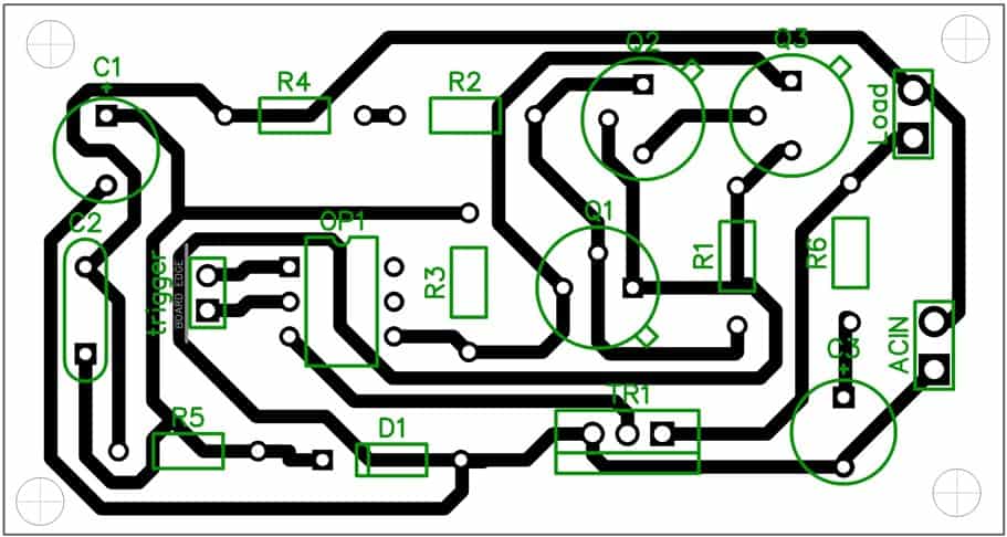
PCB Layout

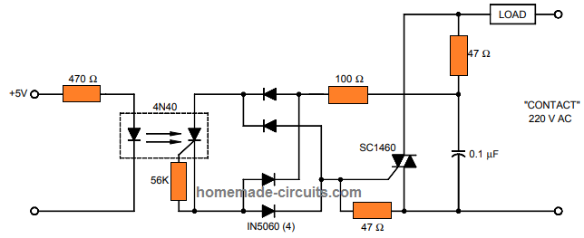
Making an SSR with SCR Opto-Coupler 4N40
The development of contemporary opto-couplers has made it incredibly simple to create high-grade solid state relays (SSRs).
Among these is the 4N40, which employs a photo SCR to provide the necessary isolated triggering of an AC load.
It is easy to setup this opto-coupler to create an SSR circuit that is both very dependable as well as efficient. As seen below, this circuit may be utilized to trigger a 220V load using a fully independent 5V logic control:

Using MOC3020 Opto-coupler IC and Triac
The advancement of modern opto-couplers has greatly simplified the process of fabricating superior solid state relays (SSRs).
One of them is the 4N40, that makes use of a photo SCR to give the required isolated AC load triggering.
This opto-coupler may be easily configured to provide an extremely trustworthy and effective SSR circuit. This circuit can also be used to activate a 220V load with a completely standalone 5V logic control, as shown below:


With the resistive nature of the SSR load, the triac TIC 226D/400 V may be employed with good results.
If the load specification calls for an inductive load, a 630 V triac—such as a type TIC 226M—might be needed.
Keep in mind that the operating voltage of capacitor C1 needs to fulfill the requirements of the employed triac.
The magnitude of the input voltage, Vin, determines the value of the input side resistor R1. The equation below is useful to determine its value:
R1 = 1000 (Vin - 1.3)/Ioc.
The current flowing across the LED in the MOC opto-coupler is shown by this formula, where Vin is measured in volts, R1 in ohms, and Ioc in milliamperes.
The computed value of R1 will be equivalent to 356 Ohms, which means that we are able to round it down to a realistically achievable value of 330 Ohms provided we assume that the LED side input of the optical coupler is Vin = 12 V and the current Ioc = 30 mA (that are the usual parameters of the MOC 3040 opto coupler).
Since the LED's current requirement Ioc in the MOC 3041 is just 15 mA, it is likely to permit the R1 limiting resistance to be as high as 680 Ohms.
This 220V solid state relay has an absolute maximum current handling capacity of about 8 amps; when dealing with larger power, modify the triac appropriately.