
The term "wireless microphone" refers to a type of handheld electronic microphone that enables users to communicate wirelessly to an amplifier in order to convey their speech.
It may be a lot of fun to build a wireless microphone at home. In this project, we'll go over one easy way to capture and transmit the sound of your voice remotely.
Introduction
When speech signals need to be magnified in order to be heard across an expanded region and distance, cordless microphone and amplifier devices are typically utilized for public address applications, theatrical amusement, or other similar events.
But considering microphones are typically kept in the hand while conversing, the device must be completely stress-free to allow the person carrying it to stroll easily throughout the premises.
We will build a basic wireless microphone circuit in this post and utilize it for the identical application mentioned above.
Understanding Microphones
A gadget that transforms speech or sound waves in the atmosphere into electrical pulses is called a microphone. Typically, they are employed for entertainment and public speaking events.
This article teaches us how to build an FM wireless microphone circuit that works without wires for the intended purpose.
The user experience was made extremely difficult and inconvenient by the wire or electrical cable that older microphone models required to connect to the amplifier.
The user used to be at risk of being entangled in the cable and maybe falling due to its messy dangling about his legs.
As a result, extremely advanced wireless microphones were developed, making them considerably more pleasant to hold and use on many platforms. Additionally, the user's proximity from the amplifier was never more a concern.
Nonetheless, the wireless microphone was made possible only by advancements in FM broadcast technological advances, as it included a tiny FM transmitter that transmitted conversations in the form of FM waves to an FM receiver prior to being amplified and delivered to the speaker systems.
The stipulated uses for these wireless microphones are still being fulfilled with success, and for certain users, they have proved extremely useful.
While its workings may appear very complex, the gadget is actually relatively simple to assemble at home, making it accessible to any enthusiast for electronics.
Undoubtedly, this is one of the most enjoyable electronic endeavors since, in addition to offering endless entertainment during construction, the builder may utilize it to show off the device's amazing wireless transmission functions with pride.
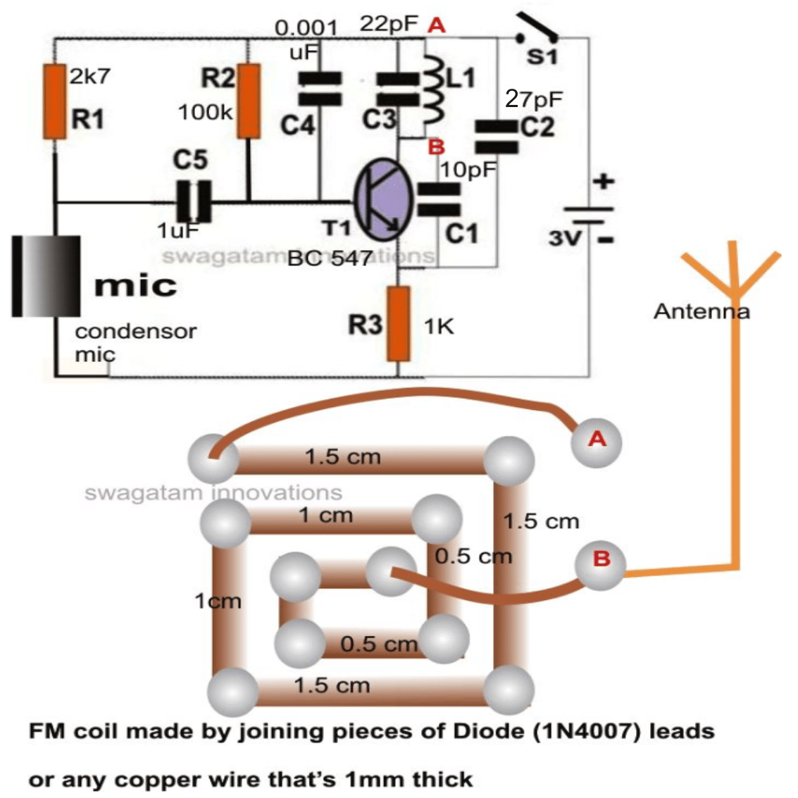
Circuit Diagram

Parts List for the wireless microphone circuit
- Resistors are 1/4 watt 5% CFR
- 2.7 k = 1
- 100 k = 1
- 1 k = 1
- Capacitors are ceramic disc
- 1 µF = 1
- 0.001 µF = 1
- 22 pF = 1
- 10 pF = 1
- 27 pF = 1
- Transistor BC547 = 1
- MIC electret = 1
- 3 V Coil Cell = 1
Construction Hints
Now let's attempt to comprehend the construction of a wireless FM microphone circuit.
The microphone part is constructed out of a tiny FM transmitter that slips into an area less than one square inch, or, if it were manufactured using surface mount technology, one square centimeter.
Because the unit's properties are so adjustable, it can really be tried with in a variety of methods.
We are able to employ button cells for the procedures because of their little power consumption.
Assuming the device is meant to be used for extended periods of speech transmission, 1.5V AAA cells would be better.
The general purpose transistor is the primary active component of the circuit, and there aren't many other auxiliary passive components, which contributes to the item's extremely low component count.
There is absolutely no need for a planned PCB for the circuit construction! In actuality, it is also not advised.
Installing the entire circuit on a little piece of veroboard is possible, or if soldering is not your thing, you could definitely put the components together across a thin layer of rubber or plastic.
The transmitter component's specifications, which are all needed to finish the wireless microphone portion, are depicted in the figure next to this one.
The circuit, battery, and switch can all be housed inside a flexible tube or other such container.
MIC Working
The key components that produce the FM carrier waves are the transistor, the inductor, and the appropriate capacitors; the arrangement closely mimics a Colpitts oscillator.
The oscillator frequency is primarily set by the capacitors C1, C2, and C3, which may also be adjusted to change the signal's reception spots across the FM radio band.
The vocal signals uttered in close proximity to the MIC are converted into electrical pulses.
As soon as the transistor's base is struck by these electrical pulses, it transforms into an audio amplifier and amplifies the signals at its collector arm.
But because the tank arrangement that generates the carrier waves additionally exists at the collecting arm, these amplified speech signals have an impact on it.
The audio signals that make up the audio broadcast in the air now begin to modify, or rather ride, the carrier waves.
Any conventional FM radio receiver can pick up the transmitted waves. However, if the device is going to be used in tandem with a high-power amplifier, it might be necessary to design an FM receiver module with a built-in headphone jack that can be easily plugged into the amplifier's LINE IN socket.
Settings for the appropriate frequency modifications are included in the readily available ready-made FM modules on the market.
These are rather compact PCB kits with independent audio, antenna, and volume control outputs as well as defaults included in.
The amplifier is the sole component that is left out of these assemblies, although we really do not require it because the amplification functionality is mostly related to the PA system, wherein the FM module must be fixed using the appropriate LINE input connections.
The FM module is conveniently housed in a compact plastic cube box, which also features an antenna in the shape of a carefully wound flexible wire and an incorporated big jack that protrudes from the box.
On the other hand, you could be using your personal portable radio for receptions as a pastime.
How to Test
After the transmitter is constructed, it could be tested by doing the quick actions listed below:
Attach a 3-volt power source to the circuit, ideally powered by two AAA pencil batteries.
A radio receiver should be placed approximately two meters away from the transmitter. Adjust the receiver until you locate the "null" spot, or the point at which the radio's "hissing" abruptly stops.
After this, clearly and loudly talk or knock into the transmitter's microphone; the sound ought to become audible through the receiver.
Proceed to move the FM radio ten meters or so farther from the transmitter and resume the process, tweaking the settings of the radio until the signal being received is impeccable.
The wireless microphone has completed its testing and is now operational.
After placing the complete component within the appropriate housing as mentioned in the previous section, you will have a functional cordless microphone. Now, though, nothing will hinder you from turning into a homemade singalong rock star.