
This article looks at an effective way to charge batteries without using relays. Rather, to complete this duty, we will use a 78XX regulator IC and a Bipolar Junction Transistors (BJTs). We will explore the detailed steps involved.
The origin of this idea is credited to Mr. Raju. He asked me further modifications in the circuit as given below.
Using a Voltage Regulator IC for Safe and Efficient Battery Charging
I have a 2N6292 transistor, but for safe and reliable SMF battery charging, I'd like to use a dedicated battery charger IC.
My friend provided a rough circuit diagram using the transistor, which I understand might not be suitable. I have an 18V 5A transformer and my friend suggested a 2200uF 50V capacitor after rectification.
Could you recommend a suitable battery charger IC for an SMF battery? Would a heat sink be necessary for the IC based on the 18V input and desired charging current?
Do these ICs typically have automatic shutoff when the battery is full? Are there any other safety features or circuit modifications I should consider for a safe and reliable charger?
Design a Battery Charger with Emitter Follower Topology
It is anticipated that the circuit will operate and cut off the battery's charging when the voltage across its terminals approaches 14 volts.
It's still uncertain if the 1 ohm base resistor value is appropriate. Precise computation is required.
A mica insulator kit can be used to install the transistor and the integrated circuit on a single heat sink. By doing this, you may potentially protect both components from overheating by utilizing the IC's thermal protection.
Circuit Diagram

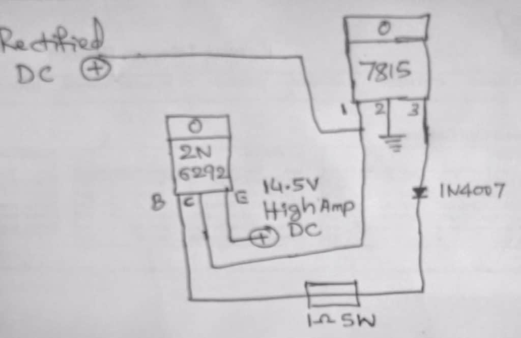
How the Circuit Works
This circuit achieves automatic cutoff when the battery reaches full capacity, providing a creative method of battery charging.
The 2N6292 power transistor is used in a common-collector transistor stage, which forms the circuit's key component. With a 0.7V loss, this setup—also referred to as an emitter follower—guarantees that the emitter voltage closely follows the base voltage.
In this configuration, the 7815 voltage regulator IC provides a controlled 15V supply to the transistor's base. This corresponds to a potential difference across the emitter (attached to ground) of around 14.3V (15V - 0.7V).
It is not required to have a diode at the base of the transistor; it can be eliminated. Its existence results in an extra undesired 0.7V decrease.
The attached battery receives a charging voltage of 14.3V. The transistor conducts and provides the required charging current as long as the battery voltage stays below 14.3V.
But as the battery gets close to being fully charged and goes over 14.3V, the 0.7V forward voltage drop across the emitter-base junction disappears. By doing this, the transistor is kept from conducting, so stopping the battery's charging current.
The charging cycle is restarted when the transistor switches back on and the battery voltage falls below 14.3V once more. The linked battery will be safely charged thanks to this constant switching.
This is the formula for figuring out the base resistor:
Base resistor = Hfe x battery internal resistance
In order to obtain optimal charging with IC 7815 IC, here is a more suitable design.

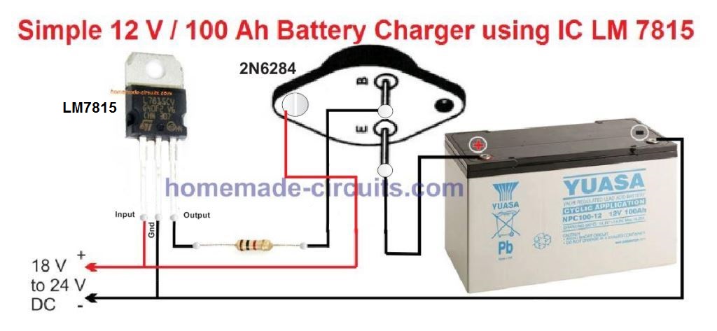
Here, in emitter follower mode, a 2N6284 is employed, as can be seen. The 2N6284 is a high-gain Darlington transistor that will allow for optimal battery charging at the targeted 10 amp rate, which explains why.
With a single 2N6284 and a potentiometer, as seen below, this may be made much simpler:

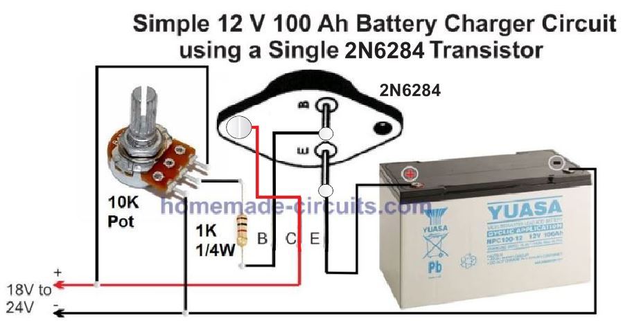
An exact 14.2 V should be obtained at the battery's emitter by adjusting the pot.
It is necessary to install the IC and the transistor on top of a large heatsink.