
An effective way to get a 24 V output from a 12 V battery is to use this high current voltage doubler circuit). The square wave signal is produced at around 1 kHz by using the 555 timer in astable mode. It functions as follows:

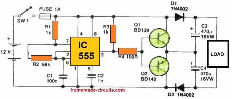
Because of the way the 555 timer is set up, capacitor C4 may be charged to almost 12 V as soon as pin 3 turns high and transistor Q1 is active. Capacitor C3 cannot discharge during this phase thanks to diode D1.
On the other hand, when pin 3 drops low, diode D2 stops capacitor C4 from discharging while transistor Q2 conducts, permitting capacitor C3 to charge similarly.
The intended 24 V output is produced by the total voltage throughout capacitors C3 and C4.
When there is no load attached, the output voltage is around 24 V; however, once a load with a 500 mA high current consumption is applied, the output voltage drops to about 20 V.
It's crucial to remember that heat sinks must be installed on the transistors in order to control the temperature produced by the high current throughout working.
TIP122 and TIP127 transistors can both be used in place of the original transistors to significantly boost the current.