
The article describes how to utilize a normal Li-Ion battery with a high-efficiency 1.5 V to 4.2 V LED driver circuit to improve lighting, prolong battery backup, and lengthen battery life.
Important Features
minimal input voltage of 1.5–4.2 V.
You may drive up to 16 LEDs at once.
LEDs with a constant current have a longer lifespan.
irrespective of the battery voltage, the LEDs promise to produce Absolute White Light with no variation in hue.
Substantial battery life and long battery backup time.
LEDs are completely protected against overcurrent and overvoltage situations.
PWM dimmable capability.
LEDs have the ability to stay lit until the very last bit of power is extracted from the battery.
How to Use IC LT1932
Designed to serve as a constant-current source, the IC LT1932 is a fixed frequency step-up DC/DC converter. Li-Ion battery LED drivers, in which the brightness of the LEDs is solely determined by the current passing through them rather than the voltage across their pinouts, are ideal for configuring with the LT1932.
The voltage range that consists of 1V to 10V is suitable for a wide variety of input supplies.
The LT1932's ability to accurately control LED current irrespective of whether or not the input voltage is higher than the LED voltage makes it perfect for battery-powered systems.
After modifying an external resistor to regulate the LED current between 5mA and 40mA, it is easy to modify the LED current employing either a DC voltage or a pulse width modulated (PWM) signal.
Absolute Maximum Rating of LT1932 IC
- VIN = 1.5V to 10V
- SHDN, Shutdown Voltage = 10V
- SW, Switched Voltage = 36V
- LED Voltage = 36V
- RSET Voltage = 1V
- Junction Temperature = 125°C
- Operating Temperature Range = -40°C to 85°C
- Storage Temperature Range = 65°C to 150°C
- Lead Temperature (Soldering, 10 sec) = 300°C
Pinout Details
SW: Switch Terminal (Pin 1). This is equivalent to the internal NPN power switch's collector. The length of the metal trace attached to this pin should be kept to a minimum in order to avoid electromagnetic interference (EMI).
Ground Connection, or GND (Pin 2). Connect this pin straight to the nearby ground plane.
LED: Light Emitting Diode Terminal (Pin 3). This functions as the internal NPN LED switch's collector. Attach the bottom LED's cathode to this pin.
RSET (Pin 4): Modify the amount of current going into the LED terminal by adding a resistor between this pin and ground. LED control is also made easier by this pin.
Pin 5 (SHDN): Input for shutdown. Wire this terminal to a voltage higher than 0.85V to turn on the LT1932; connect it to a value lower than 0.25V to turn it off.
Pin 6 (VIN): Connection for Input Power. Improve the pin bypassing by adding a capacitor to ground as near to the item as you can.
Main Operating Procedure
To regulate the output current, or ILED, the LT1932 uses a constant frequency and current mode control technique. It is easiest to comprehend how it works by looking at the block diagram below.

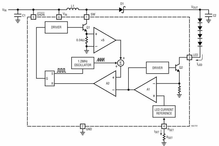
Power switch Q1 operates when the SR latch opens at the beginning of each oscillator cycle. The PWM comparator A2's non-inverting input signal is exactly proportionate to the switch current.
After that, a portion of the oscillator ramp is added to it. Comparator A2 switches off the power switch and resets the latch when the signal surpasses the limit defined by the error amplifier A1's output.
To guarantee LED current control, A1 sets the proper peak current level in this way.
If A1's output increases, more current is sent to the output; if A1's output falls, a smaller amount of current is sent to the output. Via switch Q2, A1 tracks the LED current and compares it to the current reference, that has been set up by tuning resistor RSET.
The output current, ILED, is regulated at a value of 225 times ISET, while the voltage at the RSET pin is kept at 100 mV.
Holding the RSET pin over 100 mV will reduce A1's output, which will deactivate Q1's power switch and Q2's LED switch.
Li-Ion LED Driver Application
As was previously mentioned, the LT1932 is a boost DC/DC converter that is intended to provide a constant current output. It has a set frequency output.
The item is ideal for controlling light-emitting diodes (LEDs) since it can directly control the output current.
The integrated circuit ensures that the lighting of LEDs is only reliant on the steady current passing through them, rather than the fluctuating voltage applied across their terminals.
The primary goal is to develop Li-Ion batteries to provide highly efficient LED drivers with lengthy backup times and longer battery lives.
Configuring Current LEDs
As seen in Figure above, the LED current may be adjusted by connecting a single resistor to the RSET pin.
Since the RSET pin is physically regulated to maintain a voltage of 100 mV, the current that exits this pin—designated as ISET—is essentially set to equal 100 mV divided by the resistor's value (RSET).
It's best to use a resistor with a tolerance of at least 1% to ensure accurate control.
Multiple examples of standard RSET settings with a 1% tolerance are shown in the table below.
You may use the formula below to get the right resistor value for various LED current needs.
RSET = 225 x (0.1V / ILED) .
Most white LEDs are usually run at peak currents of between 15 and 20 milliamperes.
To obtain greater brightness in higher power setups, designers can use two parallel sets of LEDs; this would culminate in a current flow across the LEDs of 30mA to 40mA (or two distinct sets, individually running at 15mA to 20mA).
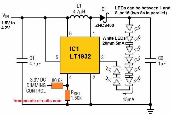
Common Application Circuit
The fundamental application circuit for powering eight LEDs using a single 3.0 V or 4.32 V Li-Ion battery is depicted in the accompanying diagram.

Safeguarding against Open Circuit
In the event that the LED chain becomes disconnected or becomes an open circuit, the LT1932 can be safeguarded through the installation of a zener diode parallel with the LEDs (see to Figure below for additional details).

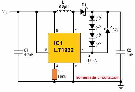
Without LEDs, the LED pin fails to supply the device with any current feedback as soon as it is switched on.
As a result, when the LT1932 operates at its maximum duty cycle, the output voltage it produces might differ by 10 to 15 times from the input voltage.
The SW pin may come into contact with voltages higher than 36V in the absence of the zener diode, exceeding its maximum rating.
Always ensure that the zener voltage is capable of sustaining more than the maximum forward voltage of the LED string in order to provide adequate protection.
PWM Adjustment for Brightness
By flashing the LEDs on and off alternately using the control signal, PWM intensity control provides a wide dimming range that exceeds 20:1.
The average current of the LEDs fluctuates according to the duty cycle of the PWM signal, which usually ranges from 5kHz to 40kHz. The LEDs can run at the maximum current or none at all.
Figure below illustrates the two possible methods for implementing PWM dimming with the LT1932.

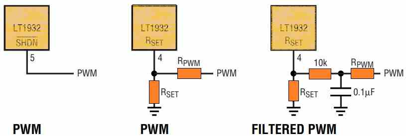
In the first instance, the LED brightness may be directly increased by increasing the duty cycle of the SHDN pin.
Applying this technique, the exact same control signal may be used to turn the LEDs entirely off or down. By completely deactivating the LT1932 and lowering the total quiescent current to zero, the signal may be set to 0% duty cycle.
As a second option, the following formula may be used to estimate the value of RPWM if the RSET pin is utilized for PWM dimming. In this calculation, VMAX stands for the "high" magnitude of the pulse width modulation (PWM) signal.
RPWM = RSET x (VMAX / 0.15V - 1)
In addition to providing a broad dimming range, PWM luminance control reliably maintains the highly genuine white LED color throughout the entire dimming range.
The true color of a white LED varies based on its ability to operate current; at a specific forward current, often between 15 and 20 milliamperes, it attains an undiluted white hue.
The emitted light starts to seem blue when this value is altered, either higher or lower. On color LCD screens, this shift typically results in an undesirable, noticeable blue tint, which is undesirable.
The LEDs turn on and off at the PWM frequency rate after the LT1932's SHDN pin is driven by a PWM control signal, as seen in the above figure.
This switching causes the average current to fluctuate with the duty cycle, alternating between running at maximum capacity and stopping altogether.
The LEDs are continually energized at the precise current level needed to produce the purest white light when they are in operation because of their dynamic working.
Whenever the LT1932 is implemented in combination with a 5kHz PWM dimming control signal, Figure below shows how the LED current behaves.
The LED current waveform follows the PWM control signal exactly and without any delays, causing the LED intensity to change proportionally with changes in the PWM duty cycle.
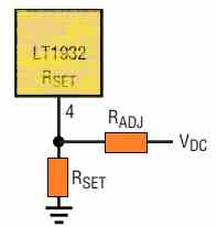
Controlling LED Brightness using a DC Voltage
Using an adjustable DC voltage to regulate LED current is a preferred method of controlling brightness in some situations.
As seen in the accompanying image, increasing the supplied DC control voltage causes current to travel via RADJ and into RSET. This lowers the current that leaves the RSET pin and, as a consequence, lowers the current flowing across the LED.

With VMAX standing for the maximum DC control voltage, ILED(MAX) for the current specified by RSET, and ILED(MIN) for the lowest ILED value while the DC control voltage is at VMAX. The RADJ value selection process should adhere to the following rules.
RADJ = 225 x {VMAX - [0.1 / ILED(MAX) - ILED(MIN)]}
Reference: LT1932 Datasheet