
This high/low temperature indicator circuit uses only BJTs and the temperature is being monitored by a thermistor.
This straightforward temperature alarm circuit is set to sound an alert (either vocally or by closing a relay contact) whenever the temperature drops or rises above a certain point.
In other words, the circuit has the ability to identify and trigger an associated warning alarm device for both overheating and underheating conditions.
The resistance of the thermistor sensor reduces as temperature rises because the sensor is an NTC (negative temperature coefficient) device.
How to Select the Thermistor
Thermistors enables the circuit to operate in the temperature range of -20 to +150°C.
The Table listed below must be referenced in order to select a thermistor for the designated tripping point, but please note that each type of thermistor can only be functional within a 30°C temperature range.

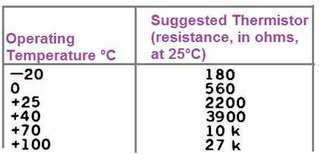
Under column 1, select your ideal temperature.
The thermistor's corresponding nominal temperature is shown in Column 2. The thermistor's resistance will be between one and four kilo ohms at room temperature.
The design could be utilized for controlling a heater or other device that regulates temperature in not-so-crtical situations because there won't be much hysteresis, across the on and off switching limits.
If higher hysteresis is needed, decrease the value of resistor R4.
Circuit Description

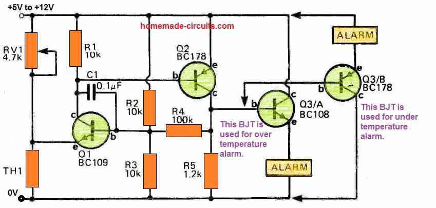
Transistor Q1's emitter is connected to a voltage divider made of a thermistor at the point of intersection of RV1 and TH1. Similar to how the thermistor TH1 changes with temperature, the voltage at Q1's emitter will also vary.
Q1 and Q2 transistors are used to make an excellent tiny Schmitt trigger. Schmitt triggers are actually just basic positive feedback amplifiers.
The preset trimpot RV1 defines the cut-off temperature below which transistors Q1 and Q2 will not conduct, or remain turned off.
The voltage at Q1's base is determined by the combination of R2, R3, R4, and R5. The parallel setup of R4 and R4 with R3 remains unchanged as Q2 is not in use.
It follows that with a 6 volt supply, the base will have 2.86 volts. If Q1's emitter voltage drops to 2.86 - 0.6 volts, or 2.26 volts, Q1 will turn on.
By connecting R4 in parallel with R2 and turning on Q2, this initiates Q2. Q1 latches on as a result, and the transistor has to be switched off by its emitter voltage rising beyond 3.14 minus 0.6 volts.
When R4's value is lowered, there will be a greater variance between these two voltages, which will increase the hysteresis.
While Q3 buffers the output of Q2, Q2 controls the relay or alarm.
This transistorized temperature alarm circuit may be used as an low-temperature alert, high-temperature alarm, or both simultaneously using the correct Q3 setup.