
Each time a high voltage or low voltage condition occurs, this AC mains high/low cut-off device will shut down or cut off the mains supply from the home's electrical system.
By doing this, it completely protects the electrical equipment and wiring in the house from fire threats brought on by low, aberrant, or overvoltages.
In order to safeguard household equipment against unexpected, hazardous high and low voltage influxes, the article explains how to build three precise automated over- and under-voltage cut-out circuits at home.
These devices may all be put in homes to regulate overvoltage and undervoltage cutoff protection.
Over Voltage and Under Voltage 220V Voltage Cut-off
Kindly examine the following diagram, which is highly comprehensible and self-explanatory.

Please leave a remark if you need help comprehending it, though.
A couple of visually contradicting aspects with the op-amp based schematic are addressed here. We respectfully ask that readers examine these points and modify the meaning as necessary:
The higher voltage limit is managed by the lower operational amplifier.
The lower voltage limit is set to be controlled by the top side operational amplifier.
Op amp A2 is assigned to preset P1.
Opamp A1 is assigned to preset P2.
Evidently, there is a contradiction between the parameter assignments.
With the exception of the aforementioned problem, the circuit is flawless functionally and will function just as described.
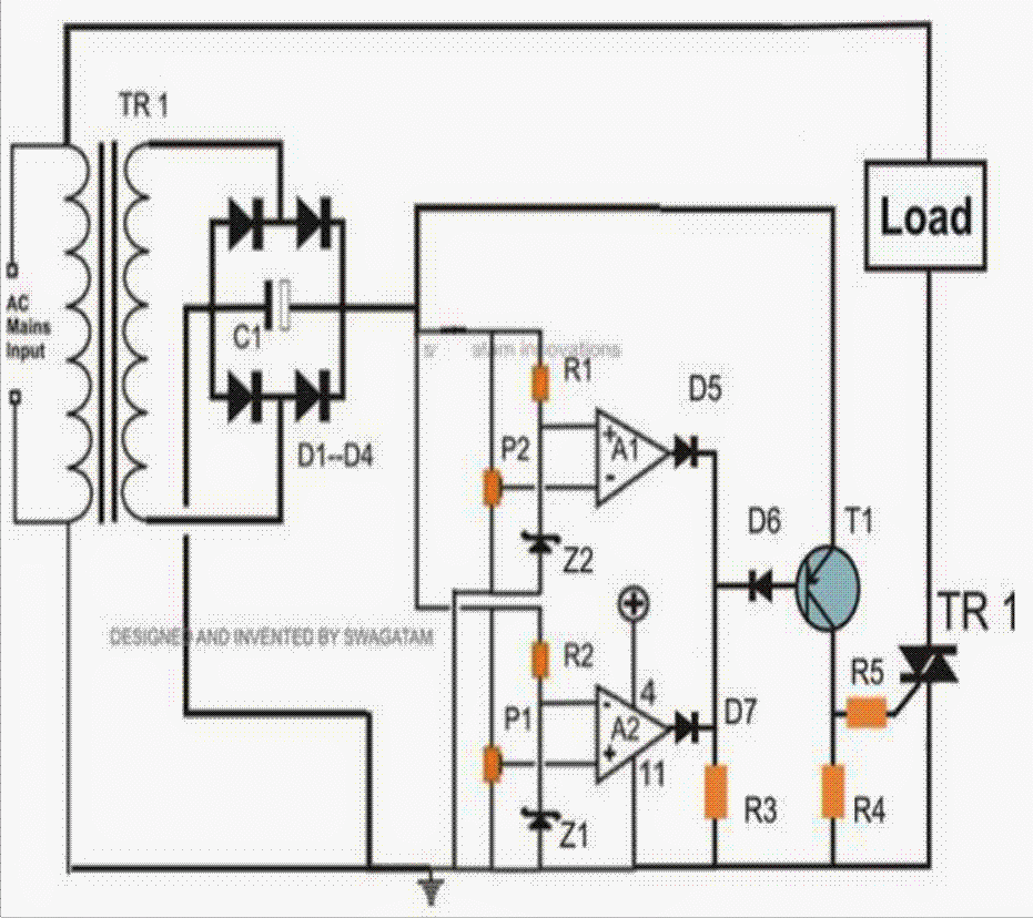
Using just a couple of op amps and a triac, the first one below describes a capacitive powered variant.
Without using a Transformer
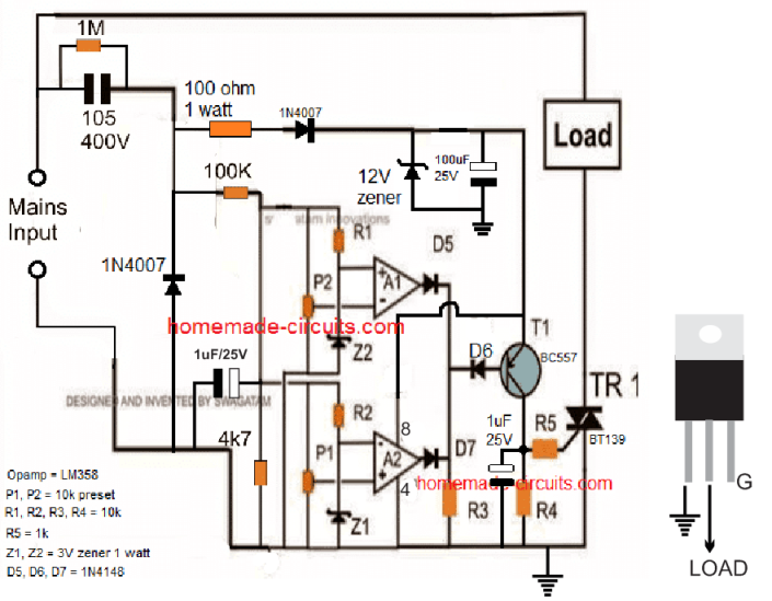
The next diagram shows the transformerless 220C AC high low voltage cut off circuit variant of the configuration described above:
Note: The circuit below is not separated from the main AC power source. Use excessive care when handling to prevent a deadly accident.

High Low Mains Voltage Control using a Relay
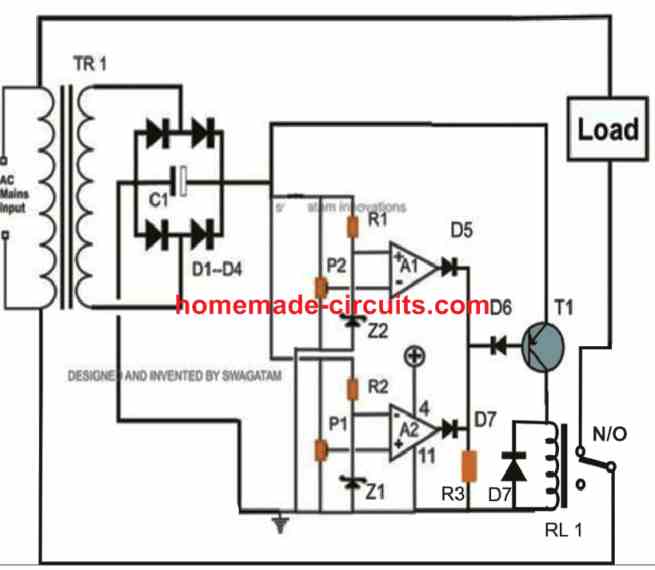
The design might be altered as seen in the accompanying picture if just one relay is to be utilized in place of a triac:

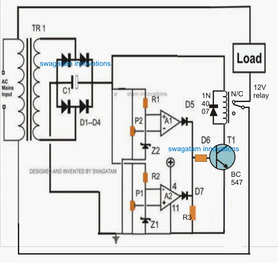
To ensure the relay doesn't vibrate during switching times, kindly provide a 22uF/25V capacitor between the transistor base and ground.
A PNP Transistor for Driving the Relay
Two opamps provided by IC LM 324 are utilized for the necessary monitoring, as can be seen in the stated mains AC high, low voltage protection circuit.
Pin #2 of the upper opamp is connected to a reference threshold, and its non-inverting input has been configured with a preset and connected to the supply DC voltage.
This allows the output of the opamp to go high immediately as the voltage at pin #3 exceeds the limit specified by P1.
In the exact same way, the lower opamp is likewise set up for some voltage limit sensing; nevertheless, because the pins are simply inverted in this case, low voltage input detection causes the op amp output to go high.
Because of this, the lower op amp reacts to a low voltage level while the top op amp adjusts to a high voltage threshold. The corresponding op amp's output goes high in response to each of the detections.
In order to ensure that the opamp output pin outs create a common output, diodes D5 and D7 are placed in series.
Hence, anytime one of the op amp outputs goes high, this originates at the junction of the D5 and D7 cathodes.
The base of transistor T1 is attached to the diode junction above. T1 is then permitted to conduct by receiving the biasing voltage through R3 as long as the output of the opamp stays low.
T1 is prevented from conducting, though, if any of the opamp's outputs go high (which might occur under unusual voltage circumstances).
Both the linked load and Relay R1 are immediately turned off. Because P1 and P2 modify the input mains to keep them inside the appropriate window level, the linked load stays ON for so long as the opamp outputs are low. P2 is configured to detect lower dangerous levels of voltage, whereas P1 is intended to identify high voltage levels.

How to Calculate the Cut-off Thresholds
The fundamental concept is to cause A1 output to become HIGH as soon as the AC mains input falls below the lower voltage cut-off limit and to cause A2 output to become HIGH whenever the mains AC exceeds the increased mains voltage cut-off point.
for as long as the input AC maintains inside the designated normal voltage range, the outputs of the A1 and A2 op amps are intended to remain LOW.
When comparing the DC output ranges across the circuit's +/- lines or across the bridge rectifier output, the mains input AC voltage variations should be highly linear.
Consequently, in accordance to the fluctuating AC mains input, the DC level across the bridge rectifier applied to the circuit will change proportionally.
Accordingly, we must first evaluate and validate the DC levels that precisely match the higher and lower mains AC cutoff limits.
The following ways can be used to accomplish this:
Using a DC voltmeter, measure the DC voltage across the bridge rectifier after removing the whole circuit from the rectifier's output.
Assuming that the voltage is 13.2 V, you should immediately switch the meter's range to AC mains voltage and measure the voltage at the transformer's AC mains side. Suppose you discover that it is 230 V.
This means that a 230 V AC input corresponds to a 13.2 V DC output.
As shown below, a straightforward cross multiplication might be used to determine the matching upper and lower limits when the aforementioned information is verified.
230/200 = 13.2/A
In this case, 230 is the standard AC input voltage.
The comparable normal DC at 230 V input AC is shown in 13.2.
It is considered that the lowest cutoff value is 200.
A represents the necessary DC with respect to the lower cutoff level of 200 V.
When we solve the above, we get:
Our lower cut-off DC at 200 V input AC is A = 11.47 V.
Similarly, the higher cut-off DC is as follows:
230/260 = 13.2/B; B is the highest cut-off DC for the high AC input of 260 V.
When we solve the above, we get:
Our higher DC cut-off voltage value, B = 14.92 V, corresponds to the high AC voltage of 260 V.
How to Adjust the Presets
We can begin setting up the two presets appropriately since we are aware of the lower and upper DC values at which the relay must activate. The next few points will help with this:
For the setting up procedures, you'll need a adjustable power supply that can generate a changeable output between less than 10 V DC and an upper limit of 15 V DC, or greater.
In the beginning set the output of the power supply to either 11.47 V or 11.50 V, which is the lower cutoff threshold.
Attach this 11.50 V to the op amp and unhook the opamp/relay circuit from the bridge rectifier circuit.
Attach a DC voltmeter to the ground wire and the A1 op amp output.
Rotate and modify the P2 setting till the A1 output turns high.
Next raise the input supply DC to a value that is somewhat more than 11.50 V, say 11.90 V.
The A1 output must turn LOW right away as a result of this.
You may verify that the lower cut-off level, which corresponds to 200 V and below, is set after you see this.
Raise the input DC range to 14.92 V, the top cut-off level, now.
After connecting the DC voltmeter between the ground line and the A2 output, start making adjustments to the preset P1 until the A2 output turns HIGH.
Reduce this level to about 14.70 V after you notice the output becoming HIGH at 14.92 V. This ought to immediately return the A2 output to LOW.
This will verify that your top cut-off limit, which is set at 260 V, is operational.
Adjust the input DC between 10 and 15 volts to further corroborate the findings. You should observe that the transistor turns off instantly as the voltage drops below 11.50 volts or rises over 14.90 volts.
It follows that only when the input DC falls between 11.50 V and 14.90 V, or the typical AC level between 200 V and 260 V, would the transistor stay in the ON position and the relay stay active (in the NO state). When these boundaries are reached or exceeded, the relay will become deactivated (in the NC position), turning off both the load and the relay.
Parts List
R1, R2, R3 = 2K2 = 3
P1and P2 = 10K preset = 2
C1 = 220uF/25V = 1
All diodes are = 1N4007 = 8
T1 = BC557 = 1
Relay = 12 V, 400Ohms, SPDT =1
op amps = 2 opamps from IC LM 324 = 1
Zeners = 4.7 volts, 400mW =1
Transformer = 12V, 500mA =1