
Essentially, the circuit for electrifying a perimeter fence that is shown here is a high voltage pulse generator. The extremely high voltage comes from an ignition coil used in many cars.
Using an astable multivibrator, the necessary frequency is produced to operate the ignition coil. The pulses that are given to the fence are managed by another astable.
Using a Fence Charger to Protect Crops
This electric fence charging equipment is just what you need if you have huge land for farming and urgently need to safeguard your plants from unwelcome visitors like animals and maybe humans.
A high-voltage, electrified barrier that shocks animals uncomfortably when touched or pushed is called an electric fence.
Therefore, such fence essentially serves as a barrier to keep both humans and animals from trespassing and from breaching the designated border.
I constructed and tested the current electric fence charger circuit, and it has shown to be powerful enough for the intended use.
Sparks Generating Many Thousands of Volts
Given that the fence charger circuit can generate voltage bursts of up to thousands of volts, it is obvious how deadly it is.
Nonetheless, because the pulses are sporadic, the victim has ample time to recognize, recover, and go.
The produced pulse is so strong that it may readily arc and fly-off across small lengths of only a few centimeters, hence the fence conductor must be sufficiently spaced to prevent leaks caused by sparking and arcing. If ignored, might significantly lower the unit's efficacy.
In this case, an automotive ignition coil (CDI Coil) is largely responsible for producing high voltage.
An ignition CDI coil's winding ratios are made expressly to generate a high-voltage arc across two tightly spaced conductors within the ignition cavity, which starts the ignition process in automobiles.
In essence, it's merely a step-up transformer with the ability to massively increase the input applied voltage at the primary winding to the secondary winding, that is the output.
Notice: When powered on, certain parts of the circuit and the ignition coil are extremely hazardous if touched. The ignition coil output in particular is excessively deadly and might potentially result in immobility. WE STRONGLY Advise USING ADEQUATE CAUTION. IF A MISTAKE IS MADE, THE AUTHOR IS NOT ACCOUNTABLE.
More in-depth analysis of the suggested electric fence charger circuit is needed.
Circuit Description
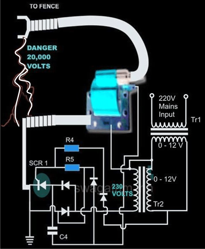
The complete circuit is essentially made up of four stages, as can be seen in the CIRCUIT DIAGRAM.
One stage of a DC oscillator,
A step-up stage that is in between 12 and 230 volts,
The ultra high voltage booster stage, as well as the firing and voltage collecting stages.
SCR2 connects the secondary windings of two step-down transformers, TR1 and TR2, to each other. The primary winding of TR1 input can be chosen based on national specifications.
But the TR2 primary needs to be qualified for 230 volts.
A typical astable multivibrator stage is formed by IC 555 and the related parts. The secondary of TR1 alone provides the circuit's supply voltage.
According to P1's parameters, the astable's output is used to activate the triac BT136 and the entire system at a certain, preset interrupted rate.
In order to instantaneously create a 230 volt potential at the opposite end of TR2, the triac links the 12 volt AC via TR1 to the secondary of TR2 throughout the ON periods.
A resistor, capacitor C4, a few diodes, and the primary operational element, SCR1, are the components of the voltage-firing stage, which receives this voltage.
The ignition CDI coil's main winding receives the firing voltage via SCR1, which is then immediately drawn to the secondary winding, which experiences a whopping 20,000 volts. It is possible to properly deliver this voltage into the fence.
It is necessary to properly apply the high voltage produced by this electric fence charger along the entire fence's perimeter.
Maintaining a minimum distance of 2 inches between the two poles of the ignition coil linked to the fence wiring is important.
The optimum element for the fence's pillars would be acrylic or a comparable non-conductive substance; metal is not recommended, and wood shouldn't ever be employed since it is prone to taking in moisture and can allow leaks.
Parts List for the explained electric fence charger circuit using SCR
- R4 = 1K, 1WATT = 1
- R5 = 100 OHMS, 1WATT = 1
- P1 = 27K PRESET = 1
- C4 = 105/400V PPC = 1
- ALL DIODES ARE 1N4007
- IC = 555 = 1
- TR1 = 0-12V/3Amp (120 or 230V) = 1
- TR2 = 0-12V/1Amp (120 or 230V) = 1
- THE SCR IS BT151 = 1
- THE TRIAC COULD BE ANY 1AMP/400V SUCH AS BT136 = 1
- TWO WHEELER CDI IGNITION COIL SHOWN IN BLUE/RED COLOR = 1
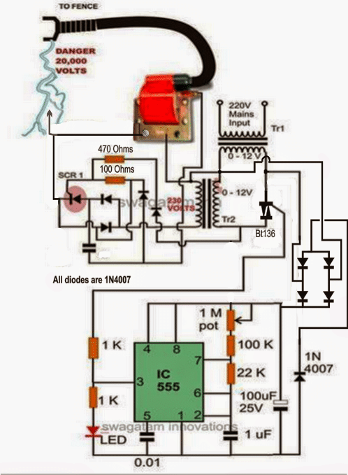
As seen below, the aforementioned idea may alternatively be carried out by producing the switching pulses for the transformer via a BJT.
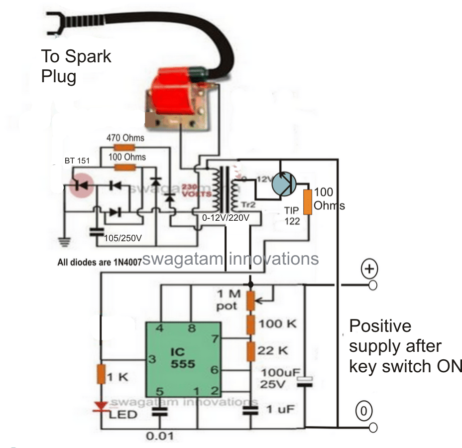
To reduce excessive transistor dissipation, consider increasing the TIP122 base resistor quantity to 10K.
To cut down on current usage, trim the 1M pot such that the IC 555's ON time is significantly less than its OFF period.
Using NOT Gates

Given that the fence charger mentioned above can run on a 12V battery, it's a good choice for isolated areas without the availability of AC power.
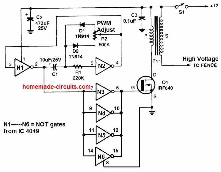
A 4049 hex-inverting integrated circuit's N1 and N2 NOT gates are used to build an oscillator circuit.
Through the pot R2, it provides a PWM control function. Using this, the output PWM may be adjusted to maximize output voltage and fence charging efficiency.
The MOSFET connects the primary winding of T1 across the 12 volt source by switching to ground anytime the positive spike of the input at Q1's gate is accessible.
There is an inhibition of current between Q1 and the transformer primary once the MOSFET gate signal goes logic low. The secondary winding of T1 produces a high voltage pulse as a result.
This results in the output of T1 producing a high voltage of approximately twenty kv. The fence and its output are able to be connected to achieve the desired electrification.
Recall that T1 can be any car ignition coil. Utilizing a two-wheeler ignition coil is advised.
Setting up Procedures
To maximize output arc and circuit efficiency, the simplest method is to adjust the potentiometer R2 to half of its value.
After that, connect a DC current meter in series with the power supply positive and the circuit.
The output of T1 is then placed around 0.5 inches above the circuit's ground line.
In order to get the highest output voltage spark and the least amount of current intake by the circuit, R2 may be subsequently tuned.
SCR and Ignition Coil Based Fence Electrification

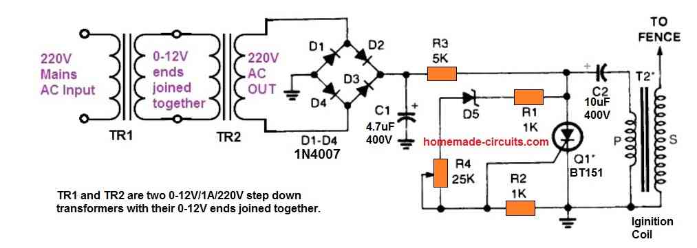
The accompanying image is another basic fence charger circuit design. The AC input voltage for this circuit can be either 220V or 120V. Thus, this circuit may only be utilized in locations with AC outlets.
With a 310V DC input, the SCR and capacitor C2 combine to create a capacitive discharge circuit.
A couple of step down transformers linked back-to-back are used to obtain the 310 V from a 220 V RMS input or the 170 V from a 120 V RMS peak voltage input.
The two 0-12V/1A/220V/120V transformers, designated TR1 and TR2, have been constructed with their 0-12V ends connected to one another.
For the planned capacitive discharge activities, this enables the circuit to receive a high voltage low current peak DC supply input.
The bridge rectifier and capacitor C1 transform the 220V or 120V from TR2 into the necessary high voltage surge supply once the AC power is turned ON.
R2 and the ignition coil's primary side are both subjected to the peak DC until C2 is fully charged. When completely charged, it generates enough voltage to turn on the zener diode D5.
The SCR is now fired and conducted by D5. C2 is released through the SCR when it trips ON. As a result, the ignition coil primary is abruptly struck by the stored peak DC inside C2.
This therefore induces an analogous high voltage on the secondary side of the ignition coil of about 20 kV. To electrify or charge the required fences, employ this 20 kV produced output.