
This article's circuit and mechanism might be regarded as the most straightforward and ideal dual axis solar tracker system available.
The Operation of the Dual Axis Solar Tracker Design
The instrument can perfectly follow the sun's movements during the day and adjust its vertical axis automatically.
In order to properly match the tracker's vertical measures, the equipment also efficiently monitors the sun's seasonal shift and advances its whole structure in a horizontal plane or in a lateral movement. This ensures that the solar panel remains pointed in the same direction toward the sun.

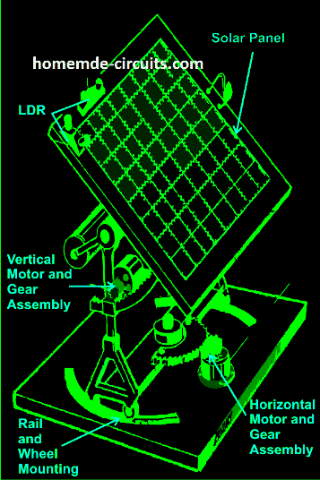
This is a rather simple method, as the illustration illustrates. Essentially, the solar tracker is positioned over some platforms and has a centrally located adjustable axis.
The panel clamps may rotate practically 360 degrees on an annular axis thanks to the pivotal structure.
The diagram illustrates the placement of a motor gear system at the corner of the pivotal axis. This mechanism is positioned to ensure that, regardless of the direction of the motor's motion, which is dependent on the sun's position, the whole solar panel moves correspondingly with regard to its central pivot while the motor turns, either clockwise or counterclockwise.
The Function of the LDR Circuit
The LDRs' placement is crucial in this situation. The combination of LDRs corresponding to this vertical plane motion has been placed in such a way that it can precisely detect sunlight and attempts to maintain the panel's perpendicularity to the sun's rays by stepping the motor's rotation in the right direction.
In reality, an electronic circuit precisely receives and interprets the LDR sensor data, directing the motor to perform the previously described functions.
One further technique works similarly to the vertical configuration mentioned above, however instead of moving the panel vertically, it rotates the entire solar panel installation in a looping motion across the horizontal plane.
Unlike vertical motions, this rotation is extremely slow and not something that is easily noticed every day because it is a reaction to the sun's location throughout seasonal changes.
Once more, the motor is moving according to an instruction from the electrical circuit, which becomes operational through the LDRs' detection.
Another pair of LDRs is utilized for the aforementioned technique, and they are positioned as indicated in the diagram, horizontally positioned above the panel.
Operating Principle of the Solar Tracker OpAmp Control Circuit
After closely examining the circuit depicted in the picture, it becomes clear that the arrangement as a whole is actually rather easy to understand.
Only two of the IC 324's op amps are used in this instance in order to complete the necessary tasks.

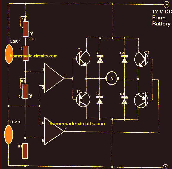
The main function of the op amp wiring is to create a type of window comparator, which is in charge of turning on its outputs when its inputs fluctuate or move outside of the preset window, which is controlled by the appropriate potentiaries.
To detect the amount of sunlight, two LDRs are attached to the op amp inputs. The outputs of the operational amplifier stay disabled as long as there is uniformity in the lighting over the two LDRs.
Nonetheless, the instant an LDR detects a variation in the light intensity above it (which might occur as a result of the sun shifting positions), the equilibrium across the opamp's input shifts in one direction, instantly raising the corresponding opamp's output.
The panel turns and regulates so it lines up with the sun's rays until an even distribution of light becomes available across the relevant set of LDRs as a result of this high output immediately activating the whole bridge transistor network and rotating the attached motor in a predetermined direction.
The outputs of the opamps are turned off, along with the motor, when the illumination level over the corresponding LDR sets back to normal.
The sun changes positions during the day, and the aforementioned apparatus moves in sync with it. This series of events repeats itself.
It is important to remember that in order to manage the dual actions, or even only to create the dual tracker solar system mechanism described above, both sets of the previously disclosed circuit assemblies are needed.
Parts List
- R3 = 15K,
- R4 = 39K,
- P1 = 100K,
- P2 = 22K,
- LDR = Normal type with a resistance of around 10 K to 40K in daylight under shade and infinite resistance in complete darkness.
- Op-amps are from IC 324 or separately two 741 ICs may also be incorporated.
- T1, T3 = TIP31C,
- T2,T4 = TIP32C,
- All diodes are 1N4007
- Motor = As per the load and size of the solar panel
How to Modify the Above Circuit to Include a Set/Reset Facility
Upon initial observation, it may seem that the circuit mentioned above lacks an automatic restore function.
A more thorough examination will reveal that this circuit does, in fact, automatically reset whenever daylight arrives or during the early hours.
The reason for this might be that the LDRs are placed under shelters that are especially made in the shape of a "V" to facilitate this behavior.
The atmosphere becomes more lighted in early morning compared to the ground due to the refraction of the sun as it comes up.
The "V"-shaped positioning of the LDRs means that the LDR facing more upward in the sky absorbs greater amounts of sunlight than the LDR facing lower down.
The panel is forced to reverse in the wee hours of the morning as a result of this circumstance activating the motor in reverse motion.
When the panel switches eastward, the relevant LDR becomes exposed to increased natural illumination from the sun's emergence. This causes the panel to move even more eastward until both LDRs are nearly correspondingly subjected to the increasing sunlight. This entirely resets the panel, restarting the entire process.

Set Reset Function
Should the need for a set reset functionality arise, the architecture that follows might be used.
When the panel completes monitoring an entire day, the set switch, which is located at the "sun-set" extremity of the tracker, becomes pushed.
The supply to the tracker circuit is provided by the N/C points of the DPDT relay, as illustrated in the diagram below. Therefore, once the "SET" switch is pressed, the relay initiates and cuts off the circuit's supply, causing the entire circuit depicted in the above article to become cut off and stops having an impact.
In order to start the procedure of flipping the solar panel to its starting position, the motor simultaneously receives the reversing voltage through the N/O connections.
The panel presses the reset switch, which is appropriately positioned at the destination, to turn off the relay yet again and reset the whole setup for the following cycle when it has completed its reversing operation toward the "sun-rise" endpoint.
