A compact high-efficiency LED tube light is a type of bulb that runs on AC mains supply to provide illumination to the area where it is mounted.
The full design specifications of a slim LED light tube light circuit employing sparkling white LEDs that are 5 mm high and 20 mA each are explained in the post that follows.
The 230V mains voltage of your home supply could be used directly to power the circuit. In addition to saving electricity, this will lessen the effects of global warming.
WARNING: WE STRONGLY ADVISE YOU DO NOT TO CONSTRUCT THESE CIRCUITS UNLESS YOU ARE ENTIRELY CONSCIOUS OF THE RISKS OF AC MAINS VOLTAGES AND REALLY HAVE INFORMATION ON HOW TO PROTECT YOURSELF BY PLANNING APPROPRIATE PROTECTION INITIATIVES, WHILE CONSTRUCTING THESE CIRCUITS, AS ALL THE CIRCUITS DISCUSSED BELOW INCLUDES DANGEROUS HIGH MAINS AC VOLTAGES.
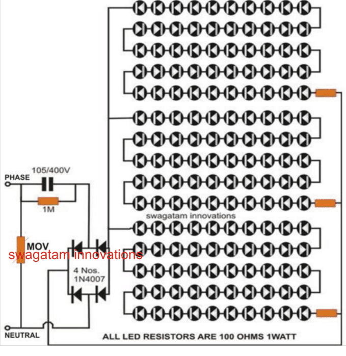
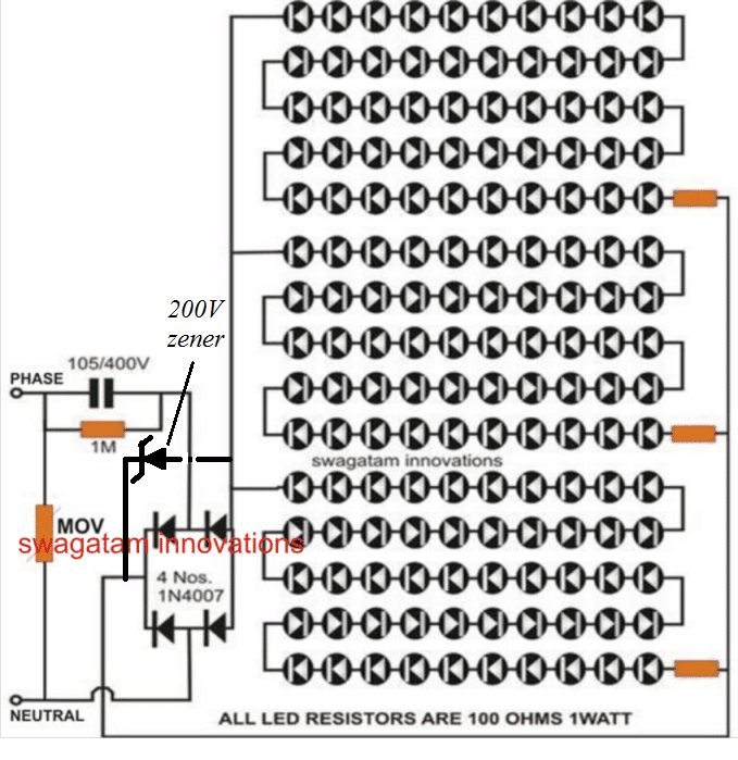
LED Tubelight using Capacitive Power Supply
If every home uses the straightforward design of an LED tube light bulb, it would not only save electricity but also contribute to lessening the impacts of global warming, which are becoming more and more severe.

The negative impacts of global warming and how it is affecting our one and only planet on a daily basis are now widely known. However, the fault for this lies with us.
Perhaps you're wondering what an average individual can do to assist in solving the issue. Examine your surroundings, and you'll see that the lights we use now contribute significantly to global warming as they produce a substantial quantity of heat.
Although CFLs are thought to be rather efficient, they also generate a significant amount of heat. The problem is readily resolved by switching out our heat-producing lights with the "cool" white LED lights.
This post will show you how easy it is to construct an LED light tube which will effortlessly replace the place of your current "heated" fluorescent tube lamps!
Parts List
You will require the following Parts for the construction:
One 36 inches long, 2 inches in diameter white PVC pipe,
150 Nos. White LEDs (5mm),
4 nos. 1N4007 diodes,
3 nos. 100 Ohms resistors,
1no. 1M resistor, 1/4 W CR 5%,
1no. Capacitor 105/400V, Polyester,
14/36 Wire for connections,
Soldering iron, solder wire etc.
How to Build
The following straightforward steps are used to make this circuit:
Partition the PVC pipe in two longitudinally.
Across the whole surface of the two PVC pipe pieces, drill holes the same diameter as an LED. Simply install all of the LEDs along the pipe as the diagrams illustrate.
Make sure that every LED has the exact same orientation and polarity position. The LED wires should be bent and snipped so that they contact side by side.
Join the solder connections to create three series of fifty LEDs each.
Verify that the specified 470 Ohm resistor is included in each series.
Interconnect the positive and negative leads of the three series LED groups in parallel using flexible wires.
As indicated in the image, combine the four diodes to form a bridge-like rectifier. Then, connect the appropriate points to the LEDs and a two-pin mains wire.
Testing it?
The easiest part of the entire process is definitely checking the compact LED tube light circuit, which can be done by following these easy steps:
Simply insert the two-pin plug into the 220V AC socket after completing the assembly process as previously said (be extra cautious since the entire circuit may include leaking 220V currents).
All of the LEDs must turn on immediately and produce a brilliant impression. Turn off the power and look for any LEDs that are connected incorrectly in terms of polarity if any of the lights in the series are dead or not lighting.
Securely attach all of the LEDs using glue to ensure they stay in the holes where they are put. Lastly, use the LEDS to connect the two parts of the PVC pipes by either binding them together or using cynoacralite bind to glue them with each other The tube's two open ends should be suitably closed.
The LED light tube circuit construction is now complete. To achieve the best efficiency and even distribution of light, it is preferable to suspend the unit from the top of the wall.
Current Control May be Crucial
Considering LEDs are sensitive to current and are susceptible to a thermal runaway, which could cause irreparable damage, current management in an LED tube light becomes essential.
Because there is no current control limit, when an LED thermal runaway occurs, the LED starts consuming greater current and gets hotter.
The LED has to consume more current due to the increasing internal temperature, which generates additional heat. This process continues until the LED is totally burned through and annihilated. The term "thermal runaway issue in an LED" describes this event.
Any LED driver circuit must have current regulation in order to prevent this.
Resistor R2 is used in this circuit to translate the mounting current to a voltage across itself.
R2 detects this voltage and instantly grounds and conducts T1's base, making it unresponsive. This quick operation starts a switching mechanism that results in the necessary current control and LED protection.
Fifty white LEDs connected in sequence make up each channel. The formula to compute R2 is as follows: R is equal to 0.7 / I, where I is the total permissible current that the LEDs used.
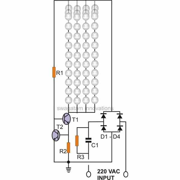
The current controlled LED tube light's entire circuit may be comprehended as follows:
How the Circuit Works
C1 suppresses the input current to an extent that is deemed safe for running the concerned electronic circuit when input AC is provided to the circuit.
The subsequent current sensing stage, which consists of T1 and T2, receives the rectified low current AC from the diodes.
T1 switches ON and fully illuminates the whole cluster of LEDs when it is first driven via R1.
T2 stays switched OFF as long as the current drawn by the LEDs, or more precisely, the current transferred by T1, stays within the designated safe boundaries. In case the current pulled by the LEDs exceeds the permissible limit, a tiny voltage across the limiting resistor R2 begins to accumulate.
As soon as the voltage approaches 0.6, T2 starts flowing voltage via its collector and emitter pinouts.
The biasing current to T1 is currently draining to ground as the collector of T2 is linked to the base of T1.
As a result, T1 is prevented from conducting fully and its collector current can therefore inhibited from increasing. Because the LEDs make up T1's collector load, the current flowing through them is also limited, protecting the LEDs from the increasing current consumption.
The presence of T1 and T2 guarantees that everything that might be harmful to the LEDs is efficiently managed and restrained.
The above spike in the current occurs as the input AC increases, creating a corresponding rise in the LED current usage.
Parts List
List of components for the current-controlled LED tube light circuit.
T1 and T2 = KST42
R1, R2 = To be calculated.
R3 = 1 M, 1/4 W
Diodes = 1N4007,
C1 = 2 uF / 400 V,