This article describes a straightforward LED torch circuit that uses a 6 volt source to illuminate three white LEDs and extend the life of your battery.
This design incorporates a handy voltage doubler circuit to create an incredibly efficient circuit with a minimal number of components.
Overview
Find out more about building it. The ability of white LEDs to produce brilliant lights at extremely low currents is well known.
However, if they are not carefully constructed, they may really be very subpar in the aforementioned regard. Discover how to optimize and create a very effective LED torch at home with this easy approach.
Six LEDs are illuminated with a 3V source.
It could be hard to properly illuminate three white LEDs at 6 volts and 20 milliamperes without using sophisticated inductor arrangements.
With its relatively strong light output and nearly endless battery life, this kind of LED flashlight may be really useful.
Furthermore, creating this exquisite circuit in your own house couldn't have been more fulfilling. As we all know, using LEDs in series yields consistently superior outcomes.
Basically, we can drive the entire series with exactly the same quantity of current needed for operating just one LED by simply increasing the necessary voltage.
When we connect three white LEDs in parallel, for instance, the total current usage is 60 mA, which is enormous and would quickly drain a tiny battery in a matter of minutes. A single white LED, on the other hand, needs only 20 mA of current at 3.8 volts to glow brilliantly.
The circuit might be extremely efficient if the aforementioned LEDs were connected in series and the voltage was increased to around 10 volts. This would allow the LEDs to be lit with just 20 mA of current.
Making an oscillator out of the IC4049 circuit
A very basic voltage stepper may be hooked up with the flexible IC 4049, which comes in a package including six inverter gates or NOT gates.
We can create the necessary buffering to the oscillator output by setting up two of its gates to function as an oscillator. Then, we'll can boost up this buffered output to drive a single series of three LEDs by connecting four of its gates in parallel.
All it would take to add more of these series would be to use extra gates (ICs) as buffers for the appropriate LED series.
To power all of these additional buffers and the LED series, one oscillator would be sufficient and could be used frequently.
Let's investigate the operation of the suggested circuit.
Circuit Description
Three white LEDs are driven by a single IC 4049 and some other passive parts at a mere 20 mA of current through a 6 volt supply, as seen in the next image.

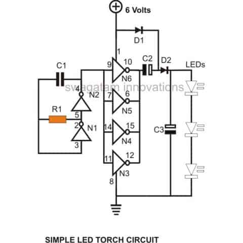
This particular setup guarantees about 100% efficiency and a long battery life.
The values of R1 and C1 dictate the frequency of the oscillator that is created by the combination of gates N1 and N2, R1, and C1.
By connecting their inputs to the oscillator's frequency output in parallel, the other four gates, N3, N4, N5, and N6, function like buffers.
Additionally, their outputs are combined into an individual common output and connected to the voltage booster circuit below.
How the Voltage Multiplier Stage Works
A voltage multiplier circuit is made with a typical layout that consists of a couple of diodes and an identical quantity of electrolytic capacitors.
The mentioned setup will effectively double the received input but is only usable with alternating voltages.
This multiplier circuit effectively doubles the applied oscillation frequency from the buffers by nearly a factor two of magnitude.
The voltage multiplier circuit's output is merged with three high-efficiency white LEDs in series to wrap up the device.
The circuit provides the LEDs with the appropriate voltage, allowing them to light up rather brilliantly.
Parts List
- R1 = 68K,C1 = 680pF,
- C2, C3 = 100 uF/ 25V,
- D1, D2 =1N4148,
- N1, N2, N3, N4 = IC 4049,
- LEDs White = 3 nos.
- GeneralPurpose PCB = As per size,
- Ni-Cd Cells = 5 nos. 1.2 volts each (rechargeable)
- Suitable Enclosure = Small plastic box to hold the circuit, batteries and the LEDs.
How to Construct
It's really simple for you to construct the circuit for this LED torch; simply gather all the parts and solder them to each other using the attached circuit diagram.
After that, all that has to be done is hook up the battery pack to the circuit and make sure it is illuminated.
If at all feasible, use a milliampere to measure the circuit's current consumption, which shouldn't be in excess of 15 to 20 mA.
Place the entire device into an appropriate acrylic box, ensuring that the LEDs stick out of the exterior of the box just enough.
Useful reflectors can be used to boost the light output. A battery pack that has been completely charged should last for approximately 5 years, even with constant use.
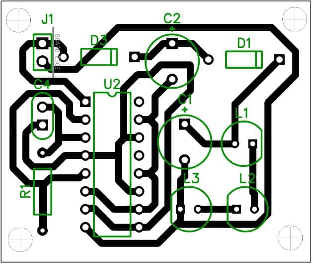
PCB Layout