
This guide will explain, how to create a basic adjustable power supply circuit using the LM317 chip and very few extra components.
As the name implies an adjustable power supply lets you change the output voltage over a certain range. You can control this with a knob that adjusts a resistor.
The LM317 is a great choice for hobbyists because it's affordable, easy to use, and lets you build a variable voltage power supply quickly and efficiently.
The Essential Role of Adjustable Power Supplies
An adjustable power supply is a cornerstone of any electronics workbench, regardless of your experience level.
It provides a variable source of power, making it useful for a wide range of tasks. From powering delicate circuits to powering motors and relays, an adjustable power supply is a must-have tool.
These power supplies come in two main forms: pre-built units readily available for purchase, or DIY projects you can build yourself using electronic components.
No matter which type you choose, a good adjustable power supply should offer some key features for reliable operation.
Key Capabilities for Reliable Performance
Adjustable Outputs:
- Voltage: A key feature is full and continuous voltage adjustability. This allows you to precisely set the voltage needed for your project.
- Current (Optional): Adjustable current is a valuable feature, but not always essential. It becomes crucial for testing circuits that require specific current limitations or for protecting sensitive components.
Voltage Regulation:
- Perfect voltage regulation is crucial. This ensures the output voltage remains stable even with fluctuations in input voltage or changes in the load (amount of current being drawn). Consistent voltage is essential for proper operation of most electronic devices.

The development of integrated circuits (ICs) like the LM317, L200, LM338, and LM723 has revolutionized building adjustable power supplies.
These chips make it significantly easier, to create circuits with the exceptional qualities mentioned earlier, including variable voltage output, adjustable current (in some cases), and stable voltage regulation.
Creating an Adjustable Power Supply using the LM317
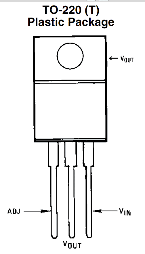
This section investigates constructing a basic power supply circuit using the LM317 integrated circuit (IC). This readily available chip comes in a TO-220 package,, and has three easily identifiable pins: input, output, and adjustment.
The input pin requires a rectified DC voltage ideally at the LM317's maximum input rating of 24 volts according to its datasheet.
The desired output voltage is obtained from the "out" pin while components controlling the output voltage are connected to the adjustment pin.
Wiring the LM317 for Variable Voltage Control

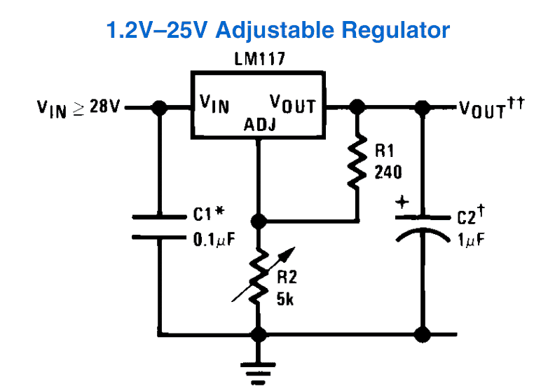
The beauty of this circuit lies in its simplicity. As you can see from the diagram it requires very few components, making it easy to build.
Adjusting the potentiometer (pot) provides linear control over the output voltage allowing you to set it anywhere between 1.25 volts and the maximum voltage supplied to the LM317's input.
While this basic design focuses on voltage control, it's worth noting, that the LM317 can also be configured for adjustable current limiting with additional components.

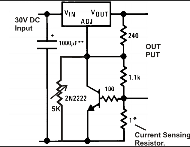
The circuit diagram demonstrates,, how the LM317 can be effectively used to generate variable voltages and currents based on your needs.
A 5K potentiometer allows you to fine-tune the output voltage, while a carefully chosen 1-ohm current sense resistor sets your desired current limit.
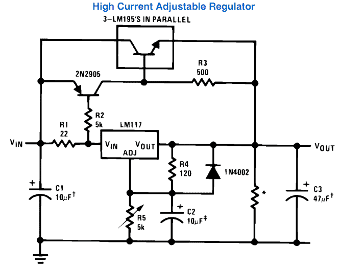
Beyond 1.5A: Adding High-Current Capability to the LM317
While the LM317 is limited to providing a maximum current of 1.5 amps on its own, it can be "boosted" to handle higher currents.
The following diagram illustrates,, how to configure the LM317 in conjunction with additional components to deliver currents exceeding 3 amps.
Important Note: It's crucial to understand that exceeding the LM317's rated specifications can lead to overheating, and potential damage to the IC.
This approach should only be attempted with proper heat sinking, and a clear understanding of the circuit's limitations.

LM317 Adjustable Voltage, Current Regulator
Our trusty LM317 (and its cousins, the LM338 and LM396) can be surprisingly versatile, and with some simple modifications, these chips can be configured as adjustable voltage and current regulators!
This concept wasn't just theory! An enthusiastic reader, Mr. Steven built and tested this very circuit. He successfully used it to drive specialized laser diodes with strict operating requirements, typically needing dedicated driver circuits.
The beauty of this LM317 configuration lies in its precision, and this makes it ideal for various applications requiring precise control over both current and voltage – not just basic power supplies!
How the Circuit Works
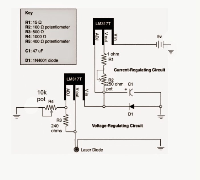
The circuit diagram appears quite manageable. It utilizes two LM317 ICs, each configured for a specific role:
- One LM317 operates in its standard voltage regulator mode which is responsible for controlling the output voltage.
- The other LM317 is configured for current control mode, which limits the maximum current delivered to the load.

Dual LM317s for Precise Control: Current Limiting and Voltage Regulation
For a more depth explanation, let's break down the circuit functionality:
- Upper LM317: The Current Regulator: This LM317 acts as the current limiter. The input power source connects across its Vin and ground pins. The current-limited output from this stage feeds into the input of the lower LM317
- Lower LM317: The Voltage Regulator: This LM317 functions as the variable voltage regulator. It receives the current-limited output from the upper stage and allows you to fine-tune the final voltage delivered to the load (laser diode in this case).
Basically, the two LM317s are connected in series. This configuration creates a foolproof system for regulating both current and voltage for the laser diode. Resistor R2 plays a key role in setting the current limit.
Simply By adjusting R2, you can control the maximum current anywhere between 5mA (when R2 is at its highest resistance of 250 ohms) and 1.25A.
This allows for precise control of the current supplied to the laser diode.
How to Calculat the Output Voltage
LM317 Output Voltage: Understanding the Formula
The output voltage (VO) of your LM317 power supply circuit can be calculated using the following formula:
VO = VREF (1 + R2 / R1)
where:
- VREF = 1.25 volts (This is a reference voltage within the LM317)
- R1 = Resistor connected between the adjustment pin (ADJ) and ground
- R2 = Resistor connected between the output (OUT) pin and the adjustment pin (ADJ)
Simplifying the Formula:
The current adjustment (IADJ) of the LM317 is typically around 50 microamps (µA). In most applications, this value is negligible compared to the other terms in the formula. Therefore, you can often ignore it for practical purposes.
This means the formula can be simplified to:
VO ≈ VREF (1 + R2 / R1)
Using the Formula:
By adjusting the values of R1 and R2, you can control the output voltage (VO) of your LM317 circuit.
This formula helps you determine the appropriate resistor values to achieve your desired output voltage.
Setting the Current Limit
The current limit for the upper LM317 (acting as the current regulator) can be calculated using this simple formula:
R = 1.25 / maximum allowed current
R = resistor value in ohms maximum allowed current = desired maximum current for your load (in amps)
For example if you want a maximum current limit of 1 amp, you would calculate the resistor value (R) as,
R = 1.25 / 1 amp = 1.25 ohms
Important Note:
The text mentions that the lower LM317 voltage regulator circuit can provide a variable output voltage between 1.25V and 30V. However with a 9V battery source, the maximum achievable voltage will be limited to approximately 9V (depending on the circuit's efficiency). This voltage can be adjusted using resistor R4.
Higher Current Capabilities:
The LM317 circuit discussed is designed to handle a maximum current of 1.5 amps, and If you require higher current for your application, you can consider replacing the LM317s with alternative ICs:
- LM338: Offers a maximum current rating of 5 amps.
- LM396: Provides a maximum current rating of 10 amps.
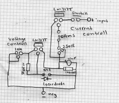
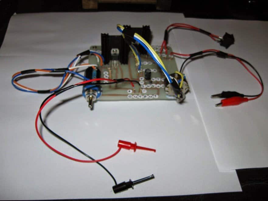
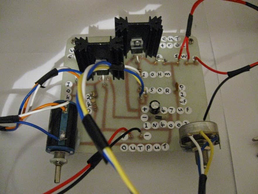
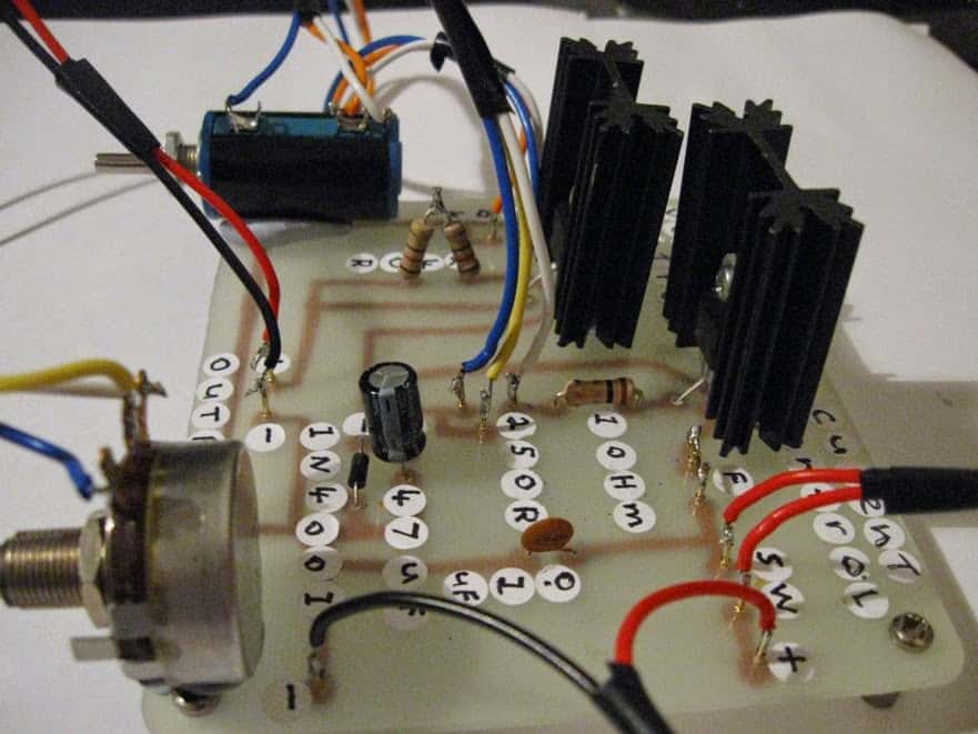
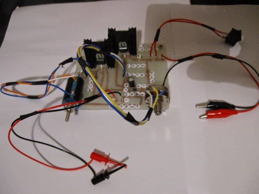
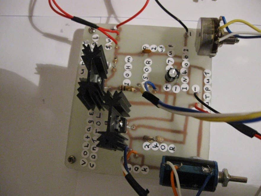
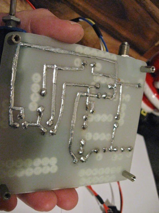
Circuit Verification:
The text concludes by mentioning that Mr. Steven successfully built, and tested the circuit, including sharing images.
Prototype Images
Adding Push-Button Control to Your LM317 Power Supply
We've explored how to configure an LM317 for adjustable output using a potentiometer. Now let's go deeper into using push buttons for digitally controlled voltage selection.
This approach eliminates the mechanical potentiometer and replaces it with push buttons for "up" and "down" selection of desired voltage levels, and This innovation transforms the traditional LM317 power supply into a more digital design. It removes the potential for wear and tear, associated with a traditional potentiometer, that can lead to erratic operation and inaccurate voltage outputs over time.
The following diagram shows, the modified LM317 circuit designed to respond to push-button selections for voltage control.

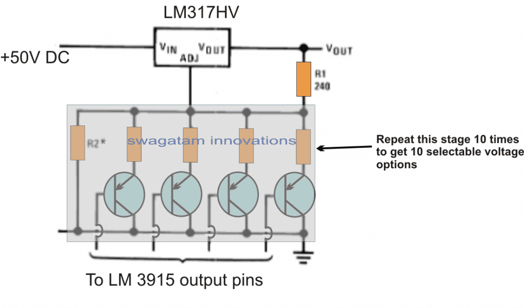
Calculating Resistor Values for Push-Button Voltages
The values of the R2 resistors need to be calculated in relation to the fixed resistor R1 (240 ohms) to get the desired voltage levels,, corresponding to each push button press.
References: http://www.ti.com/lit/ds/symlink/lm317.pdf