
In order to charge small batteries, like a 12V 7AH battery, at home, a basic solar panel regulator controller circuit may be constructed by following the instructions in this post.
Using a Solar Panel
We're all rather knowledgeable about solar panels and how they work. The primary purpose of these incredible gadgets is to transform solar radiation or sunlight into electrical power.
In essence, a solar panel is composed of discrete photovoltaic cell portions. Small amounts of electricity, typically between 1.5 and 3 volts, can be produced by each of these cells.
A large number of these cells are connected in series across the panel, generating an effective voltage of 12 or 24 volts while the device as a whole is operating.
The amount of light that strikes the panel's surface directly relates to the unit's current generation.
Typically, a lead acid battery is charged using the energy produced by a solar panel.
When completely charged, the lead acid battery is utilized with an inverter to generate the necessary AC mains voltage to power the electrical appliances in the house. For the panel to perform at its best, the sun's rays should ideally be incident across the surface.
The solar panel must, however, continuously monitor or follow the sun's motion in order to produce power at an efficient rate because the sun is never static.
One of my previous posts may be of interest to you if you want to design an autonomous twin tracker solar panel system.
Only around 30% of the solar panel's potential will be converted if there is no solar tracker installed.
Returning to the topic at hand, solar panels are arguably the central component of the system for transforming solar radiation into electrical power. Nevertheless, significant dimensioning must be done on the energy produced before it can be utilized efficiently in the previous grid tie system.
Why do we Need a Solar Regulator
When it comes to the sun's location, its rays' strength, and its angle of convergence over the solar panel, the voltage obtained from a solar panel is hardly constant and changes greatly.
When used to charge a battery, this voltage has the potential to damage the battery and its related components, leading to unnecessarily high temperatures that might endanger the entire system.
A voltage regulator circuit is often employed between the solar panel output and the battery input for the purpose to control the voltage from the solar panel.
The secure value needed by the battery to charge is never exceeded by the voltage from the solar panel thanks to this circuit.
Solar panels often have a minimum voltage output that is higher than the voltage needed to charge a battery in order to provide the best possible outcomes.
Essentially, this means that the solar panel needs to be able to provide a voltage greater than, say, 12 volts, that could represent the battery voltage when charging, even in unfavorable situations while the sun's rays are not as strong or ideal.
Circuit Diagram

NOTE: PLEASE REMOVE R4, AS IT HAS NO REAL IMPORTANCE. YOU CAN REPLACE IT WITH A WIRE LINK.
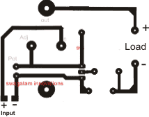
Track side PCB Design (R4, Diode and S1 not included...R4 is actually not important and may be replaced with a jumper wire.
How it Works
With reference to the suggested circuit for a solar panel voltage regulator, it is apparent that it is designed to meet our specifications while utilizing relatively common components.
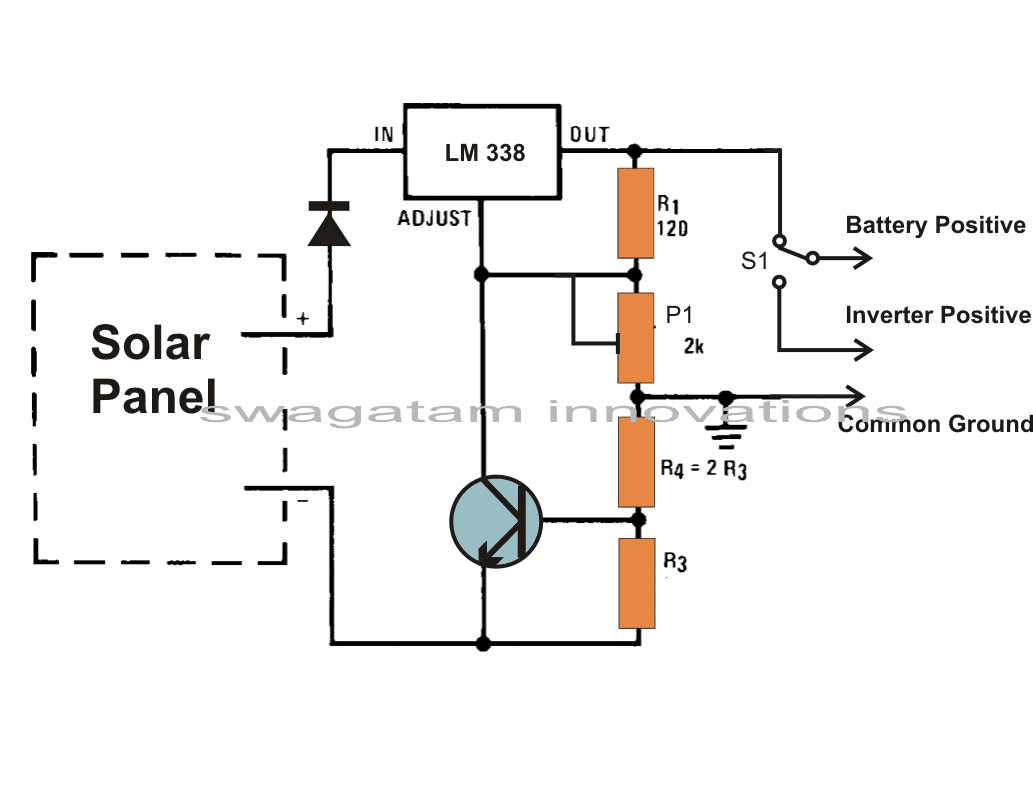
The centerpiece of the whole setup is a single integrated circuit (IC) called LM 338, which is in charge of enforcing the necessary voltage limits all by itself.
The solar panel regulator circuit displayed is constructed using the IC 338 standard mode.
The battery's output is obtained at the IC's output, and the input is supplied to the points of the IC that are visible.
The voltage level that might be regarded as the battery's safe value is precisely adjusted via the pot or preset.
Current Controlled Charging
In order to ensure that the battery never gets an over current and always gets a constant predetermined charging current rate, this solar regulator controller circuit also has a current control function. The wiring of the module can follow the diagram's instructions.
Even a layperson may easily wire the stated necessary places. The regulator circuit handles the remaining functions.
As soon as the battery is completely charged (as displayed through the meter), the switch S1 has to be switched to inverter mode.
Calculating Charging Current for the Battery
By choosing the resistor R3's value suitably, one may choose the charging current.
The formula may be solved as follows: 0.6/R3 = 1/10 battery AH
Adjusting the preset VR1 allows the regulator to supply the necessary charging voltage.
Solar Regulator with Adjustable Voltage and Current Output
The LM338 ICs are used in the high current voltage regulator circuit depicted in the accompanying image.
Several LM338 Ics are connected in parallel atop the same common heatsink to obtain the high current.
Although they are not included in the design, you might connect a minimum of eight LM338 ICs in parallel when assembling it actually.

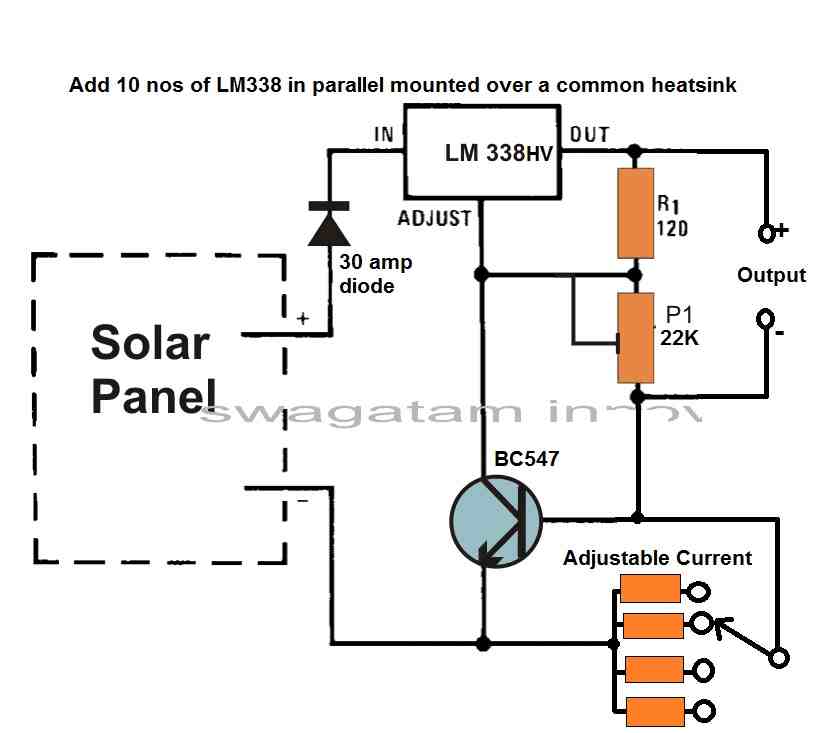
The LM338 HV IC allows for an input voltage of up to 50 V.
Using a resistor ladder to change the resistance at the base of the BC547 transistor, current may be controlled.
The circuit may be able to withstand higher currents when more LM338 ICs are connected in parallel and share the load current.
It is important to keep in mind that different integrated circuits may have different output voltages, which might lead to unequal load current sharing.
To prevent this, use a small resistor (like 0.1 ohms) in series with the output of each integrated circuit to balance the current sharing.
As previously stated, however, in order to allow for shared heat dissipation and equal IC conductivity, the ICs must be linked over a single common heatsink. It might thus not be necessary to add a 0.1 ohm resistor.
By altering the resistance at the transistor's base, the BC547 transistor, which is linked to the LM338's ADJ pin, functions as a current sink for the IC, enabling the current to be changed.
It is simple to choose the appropriate current level thanks to the resistor ladder that is attached to the transistor's base.
All things considered, this design uses the LM338 ICs in tandem to give a high current, adjustable voltage control solution.
To avoid thermal problems, it's crucial to make sure the heatsink can manage the heat dissipation of several ICs running at high currents.