
You won't have to worry how to wire led lights anymore after reading this article, which will teach you how to create your own customized LED displays and calculate LEDs in series and parallel using a straightforward formula. but know the specifics here and can really pull it off.
In addition to their eye-catching color visuals, LED lights are renowned for their dependability and low power usage.
Additionally Large alphanumeric displays that may be used as indicators or ads can be created by wiring LEDs in clusters.
Why Calculating LEDs is Crucial
While creating LED displays may be enjoyable, we frequently find ourselves wondering how to interconnect LED lights. Discover how easy it is to create your own LED displays using a formula.
As we currently know, an LED needs a specific forward voltage (FV) in order to light up. For instance, the FV of a red LED is 1.2 V, that of a green LED is 1.6 V, and that of a yellow LED is around 2 V.
Regardless of hue, all contemporary LEDs are designed to have a forward voltage of around 3.3V.
However, adding a current-limiting resistor along with an LED becomes essential since the supply voltage provided to an LED is typically higher than its forward voltage value.
So let us see how to determine a current limiter resistor for a particular LED or set of LEDs.
Calculating Current Limiter Resistor
The following formula could be used to get the magnitude of this resistor:
R = (supply voltage VS – LED forward voltage VF) / LED current I
Here, R stands for the relevant resistor in ohms.
The LED's supply voltage input is denoted by Vs.
The LED forward voltage, or VF, is the lowest supply voltage that an LED needs to function at maximum brightness.
To find the "total forward voltage" for a series LED configuration, simply multiply the FV for every LED with the sum of the number of LEDs in the series. This formula simply needs to be used in place of the "LED forward voltage." This number becomes 3 x 3.3 = 9.9 if there are three LEDs connected in series.
LED Current, also abbreviated as I, is the LED's current rating; it can range from 20 mA to 350 mA, contingent upon the LED's specifications. The formula requires that this be translated to amps, thus 20 mA becomes 0.02 A, 350 mA equals 0.35 A, and on and so forth.
Correct Way to Connect the LEDs?
In order to comprehend this, let's read the following conversation:
Suppose for the moment that you wish to create an LED display with ninety LEDs and a 12V power source.
You must properly interconnect the LEDs in series and parallel in order to correctly align and customize the 90 LED with the 12V supply.
Three parameters must be taken into account for this computation, and they are as follows:
In this case, there are 90 LEDs total.
For ease of computation, we will assume that the forward voltage of the LEDs is 3V, even though it is actually 3.3V.
The supply input, the one in this case is 12 V
Priority one should be given to the series connection specification and the number of LEDs that can be accommodated within the specified supply voltage.
Divide the source voltage by three volts to do this.
Naturally, the response is 4. This indicates the maximum number of LEDs that the 12V supply can support.
Nevertheless, the aforementioned requirement would not be wise since it would limit the ideal brightness to a rigid 12V supply and result in decreased LED light output should the supply be decreased to a lower voltage.
As a result, it would be wise to increase the LED number from one to three in order to guarantee a smaller margin of at least 2V.
Thus, three LEDs connected in series with a 12V supply seems suitable, and this would guarantee that the LEDs continue to light up rather strongly even if the voltage was lowered to as low as 10V.
Given that we now have 90 LEDs, we would like to know what number of these three LED threads can be created. As a result, 30 is the result of dividing the entire number of LEDs—90—by 3.

This means that 30 LED sequential strands or chains, with 3 LEDs in each string, would require soldering. That's rather laid back, correct?
It should come as no surprise that each of the 30 LED strings has a positive and a negative free end once you have assembled them all.
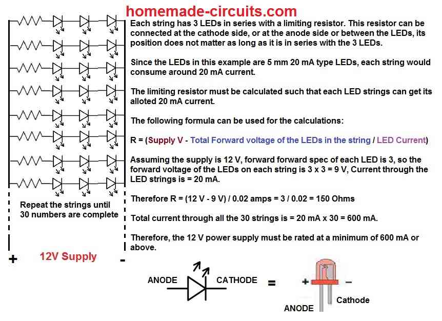
The resistor could be connected to either the positive or negative end of the string; its position is irrelevant as long as it is in the middle of the sequence. You may even position the resistor halfway between the LED series. The calculated resistor value from the earlier part should then be connected to any one of the free ends of each series. By using the previously mentioned formula, we determine the resistance for every LED strand to be:
R = (supply voltage VS – LED forward voltage VF) / LED current
= 12 - (3 x 3) / 0.02 = 150 ohms
Imagine for the moment that we wire each negative end of an LED string to this resistor.
Following that, you may start connecting each series' negative or resistor ends as well as the common positive ends of the LEDs.
Lastly, connect these common ends to a 12-volt supply using the proper polarity. Upon initial inspection, the entire design will exhibit a consistent, dazzling light.
These LED strings may be arranged and aligned to fit the display's design.
Calculating LEDs with Odd Number
When the number of LEDs in your LED display is strange, anything can happen.
For instance, if the display in the aforementioned scenario had included 101 LEDs rather than 90, and the supply was 12V, it would have been difficult to divide 101 by 3.
Thus, we determine that 99 is the closest number that is directly divisible by 3. 33 is the result of dividing 99 by 3.
Consequently, the computation for these 33 LED strings would be as previously described, but what about the two LEDs that are left? Fear not—we can still link these two LEDs together and connect them in parallel with the other thirty-three strings.
Nonetheless, we compute the series resistor appropriately to guarantee that the two LED strings accepted the same amount of current as the other three LED strings.
We just need to alter the total forward voltage in the formula, as shown below:
R = (supply voltage VS – LED forward voltage VF) / LED current
= 12 - (2 x 3) / 0.02 = 300 ohms
This allows us to know the resistor value that corresponds to the two LED series individually.
As a result, each of the three LED strings has 150 ohms, and the two LED strings have 300 ohms.
By connecting a suitable compensatory resistor in series with the appropriate LED strings, you may rectify LED strings that have different numbers of LEDs.
Therefore, by altering the resistor value for the rest of the smaller series, the problem may be readily remedied.
Our lesson on connecting LEDs in series and parallel for any number of LEDs with a given supply voltage is now complete. If you have any questions, please use the comment box to obtain the answer.
Using Calculated Series Parallel LEDs in Display Board
Thus far, we have studied the series and parallel calculation and connection of LEDs.
We will look into how to connect LEDs in series and parallel to create a huge numerical LED screen in the sections that follow.
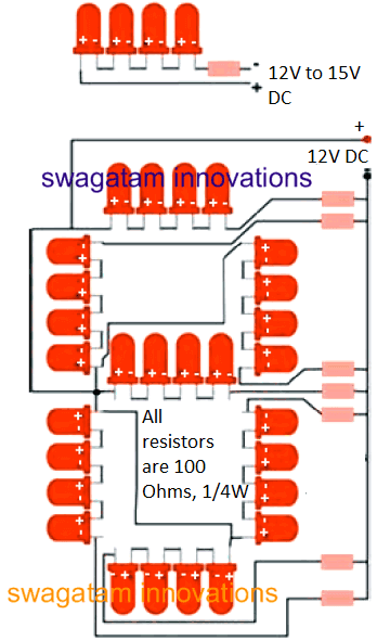
We'll create an LED figure display, "8," as a prototype and examine its wiring.
Parts Required
You will need the following handful of electronic components for the construction:
RED LED 5mm. = 56 nos.
RESISTOR = 180 OHMS ¼ WATT CFR,
GENERAL PURPOSE BOARD = 6 BY 4 INCHES

Calculating an LED Display?
This number display circuit is quite easy to create, and it goes like this:
Place every LED into the general-purpose board, being sure to align them according to the circuit diagram's instructions.
At first, solder just one lead per LED.
Once this is finished, you will discover that the LEDs are attached somewhat irregularly rather than straight.
At the same time as you touch the soldering iron tip to the soldered LED point, press down on the specific LED to push its base flat on the board. To position the LEDs straight, repeat this process for each LED.
Proceed to solder the remaining unsoldered lead of every LED. Use a nipper to cut their leads neatly. Common up the positives of each LED series in accordance with the circuit design.
Each series' negative open ends should be connected to 180 ohm resistors. Once more, make sure all of the resistors' free ends are common.
The "8" LED display's construction is now complete. Only need to connect a 12 volt source to the common resistor negative and the common LED positive to check it.
In the shape of a huge numerical display, the number "8" should appear promptly and be recognizable even from a distance.