
This post dives into calculating component values for transformerless power supplies, using basic formulas like Ohm's Law.
Understanding the Circuit:
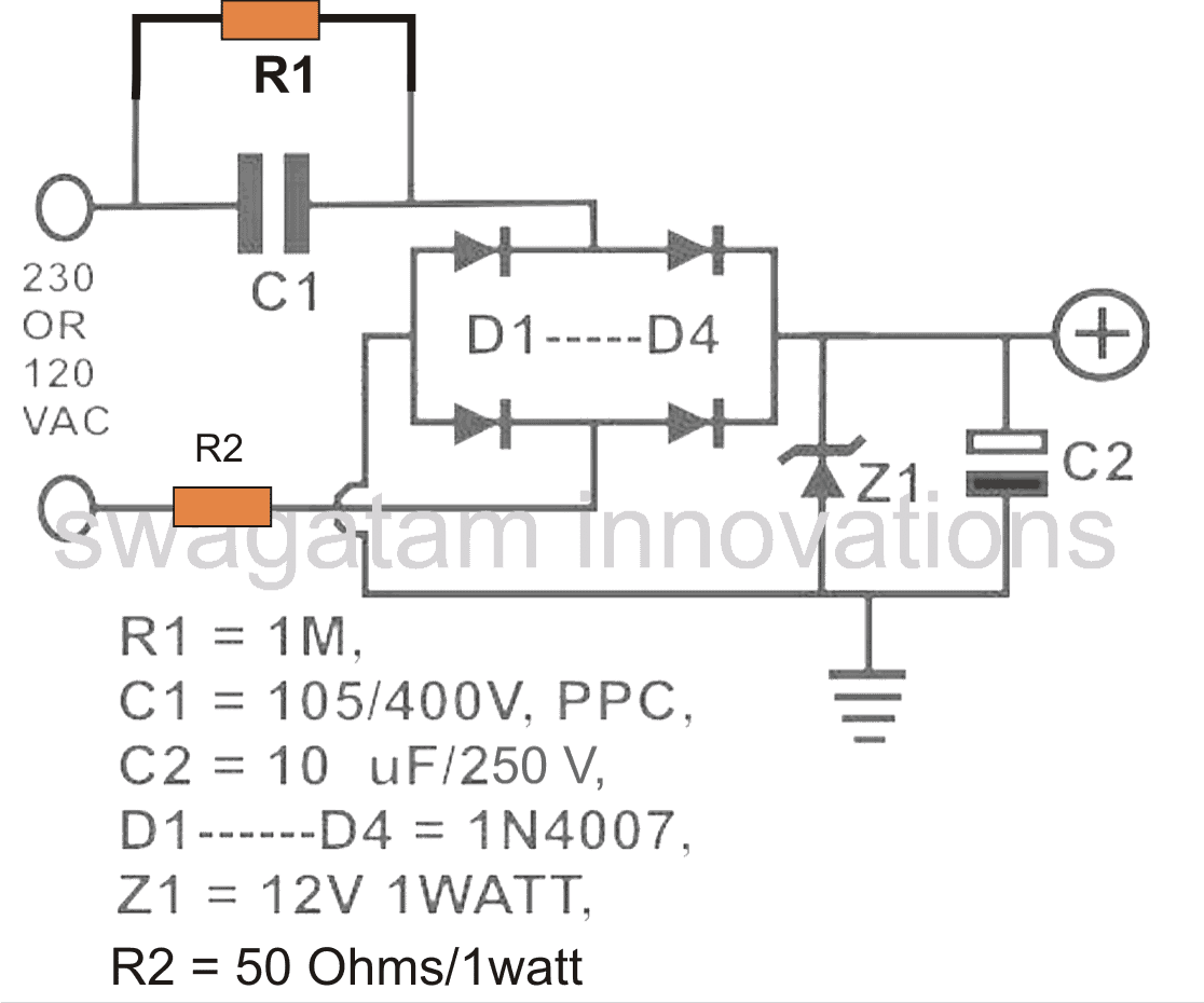
Before we jump into calculations, let's break down a typical transformerless power supply circuit (refer to the diagram for reference):
- C1: This large capacitor plays a critical role. It reduces the dangerous mains current to a safe level for your device.
- D1-D4: These diodes form a bridge rectifier, converting the lowered AC voltage from C1 to pulsating DC.
- Z1 (Optional): A Zener diode can be used to regulate the output voltage to a specific level.
- C2: This capacitor acts as a filter, smoothing out the pulsating DC from the bridge rectifier and providing a cleaner DC output for your device.
- R2 (Optional): A resistor can be used to limit the initial surge of current when the circuit is powered on. However, a thermistor (NTC) is generally preferred for this purpose.
Ohm's Law and Transformerless Power Supplies:
Ohm's Law (V = IR) is a fundamental tool for electronics calculations. However, using it with transformerless power supplies and LEDs can be tricky due to the unique characteristics of these circuits.
Calculating Current and Voltage:
Transformerless power supplies typically output low current but maintain a voltage close to the mains voltage (until a device is connected). For example, a 1uF capacitor connected to a 220V mains (resulting in roughly 308V after rectification) might provide a maximum current of 70mA initially. This voltage will gradually decrease as you connect a device and draw current.

The Impact of Current Draw on Voltage in Limited Power Supplies
- If a load uses the entire available current (70 mA in this case), the voltage will plummet to near zero.
- Since the voltage drop is proportional to current draw (linear relationship), we can calculate voltage drops for various load currents.
- Dividing the initial voltage (308V) by the maximum current (70 mA) gives us a voltage drop rate of 4.4 volts per 1 milliamp (mA) of current increase.
- This means a 20 mA load will cause an 88-volt drop (20 mA * 4.4V), resulting in a final output voltage of around 220 volts (308V - 88V).
- For example, connecting a 1-watt LED directly would consume most of the current, leaving a voltage close to the LED's forward voltage (around 3.3V). This happens because the LED prioritizes current flow.
- However, the LED voltage won't drop to zero because it has a built-in limit (forward voltage) that prevents excessive voltage drop across it.
Key takeaway:
In power supplies with limited current capacity, the voltage level becomes less important compared to the amount of current it can deliver safely.
Additional Notes:
- An LED can handle 30-40 mA at its forward voltage, but higher currents at higher voltages can damage it.
- The crucial aspect is to ensure the maximum current drawn by the load stays within its safe operating limit.
Resistor Selection in the Circuit:
- LED Current Limiting: If an LED is the load, a carefully chosen capacitor can limit current to a safe level, potentially eliminating the need for a resistor altogether. This relies on the capacitor's reactance to control current flow.
- Resistor for High Current Loads: If the capacitor allows too much current for the load (as discussed earlier), a resistor can be added to bring the current down to a safe operating range.
Surge Protection Resistor (R2):
- Purpose: Resistor R2 protects the circuit, especially the LED and zener diode, from a surge of current during startup.
- Surge Current: When the circuit turns on, capacitor C1 acts like a short circuit for a brief moment, allowing the full 220V to initially appear across the output. This surge can damage sensitive components.
- Zener Protection: R2 is chosen based on the zener diode's specifications, particularly its maximum current and power dissipation ratings. In this example, a 1W, 12V zener allows a maximum current of 0.083 amps. Ideally, R2 should be 12V / 0.083A = 144 ohms.
- Practical Considerations: Since the surge is momentary, a lower resistance than 144 ohms can often be used in practice.
- Input Voltage and Surge Current: We don't consider the 310V input voltage for calculating R2 because the capacitor limits the current to 70 mA.
- NTC Thermistor for Optimal Current: A Negative Temperature Coefficient (NTC) thermistor is a better choice for R2. It limits current only during startup and then allows the full 70 mA to flow normally.
Discharge Resistor (R1):
- Purpose: Resistor R1 safely discharges the stored voltage in capacitor C1 when the circuit is unplugged.
- Balancing Speed and Heat: The ideal R1 value is as low as possible for fast discharge but high enough to avoid excessive heat dissipation while connected to the mains. A 1/4 watt resistor can't dissipate more than 0.25 watts / 310 volts = 0.0008 amps (0.8 mA).
- Calculating R1: Based on the power dissipation limit, R1 should be around 310 volts / 0.0008 amps = 387500 ohms, which is approximately 390 kilohms.
Choosing the Right Resistor for Your LED
This example shows a circuit where the capacitor allows too much current (70 mA) for a typical LED. We'll calculate the resistor value using the standard LED resistor formula:
R = (Supply Voltage - LED Forward Voltage) / Desired LED Current
Following the formula:
- Supply Voltage (VS): We initially used 220V, which might not be correct depending on the circuit setup.
- LED Forward Voltage (VF): This is typically around 3.3V for red LEDs.
- Desired LED Current (IL): In this example, we want 20 mA (milliamps).
Initial Calculation with Incorrect Voltage:
- Using 220V for VS: R = (220V - 3.3V) / 0.02A = 10.83 kΩ (kilohms)
- This value seems high and would dim the LED. The high supply voltage might be a mistake.
Recalculating with Adjusted Voltage:
- If the LED directly receives the full voltage drop across the capacitor (around 3.3V): R = (3.3V - 3.3V) / 0.02A = 0 ohms (not ideal)
- This calculation isn't practical because a 0-ohm resistor would short-circuit the power source. In reality, there will be some voltage drop across other components.
Using a Zener Diode:
- If a Zener diode regulates the voltage before the LED (e.g., 12V), use the Zener voltage instead of the full supply voltage: R = (12V - 3.3V) / 0.02A = 435 ohms
Choosing a Practical Resistor Value:
- Due to component variations and practical considerations, a resistor value around 400 ohms is a good starting point for a red LED with a 12V Zener diode and a desired current of 20 mA.
The Importance of Capacitor Selection in Transformerless Power Supplies
In transformerless power supplies, capacitor C1 plays a critical role. Its size directly impacts the output current and needs careful selection to match the load requirements.
- Large Capacitor Risks: Choosing a capacitor too large for a small load can cause:
- Excessive inrush current: A high surge of current when the circuit turns on, potentially damaging the load.
- Optimal Capacitor Selection: A properly sized capacitor ensures:
- Controlled inrush current: Limits the initial surge to a safe level.
- Nominal power dissipation: Minimizes heat generation within the capacitor.
- Adequate load safety: Protects the connected device from excessive current.
Ohm's Law and Capacitors in Transformerless Power Supplies
Ohm's Law (I = V/R) is typically used for calculating current in resistive circuits. However, in transformerless power supplies, capacitors are often used to limit current.
The challenge is that Ohm's Law doesn't directly apply to capacitors because they don't have a constant resistance like resistors.
Their opposition to current flow is called reactance (Xc), which is frequency-dependent.
Finding the Equivalent Resistance of a Capacitor:
To utilize Ohm's Law for a capacitor-limited circuit, we need to find a way to express the capacitor's current-limiting ability in terms of resistance.
This can be done by calculating the capacitor's reactance (Xc) at the operating frequency of the circuit and then converting it to an equivalent resistance.
Deriving a Method for Equivalent Resistance:
There are established formulas for calculating reactance based on capacitance (C) and frequency (f).
By manipulating these formulas and Ohm's Law, we can derive a method to translate the capacitor's reactance into an equivalent resistance that can be used in the Ohm's Law equation to determine the current in a transformerless power supply with a capacitor as the current limiter.
Capacitive Reactance: The Key to Current Limiting
While capacitors don't have resistance like resistors, they do oppose current flow with a property called reactance (Xc). This reactance acts like a resistance for our calculations.
Calculating Reactance:
The formula for reactance is:
Xc = 1 / (2πfC)
where:
- Xc = reactance in ohms
- π (pi) = a mathematical constant (approximately 3.14)
- f = frequency in Hertz (Hz)
- C = capacitance in Farads (F)
Example: Finding the Current Limit of a Capacitor
Let's see how much current a 1uF capacitor can handle at 50Hz (common mains frequency):
- Calculate reactance (Xc):
Xc = 1 / (2 x 3.14 x 50 x 0.000001 F) ≈ 3184 ohms
- Apply Ohm's Law to find current (assuming 220V mains voltage):
I = V / R = 220V / 3184 ohms ≈ 0.069 amps (or 69 mA)
This tells us the capacitor can safely handle a maximum current of around 69 mA.
Using Reactance for Other Capacitors:
By following these steps and using the reactance formula, you can calculate the maximum current rating for any capacitor in a transformerless power supply, considering the operating frequency.
Important Safety Warning:
WARNING: Transformerless power supplies are directly connected to the mains voltage and can be extremely dangerous. The entire circuit may be at mains potential and pose a lethal shock hazard. Only handle such circuits with extreme caution and proper safety training.