
A bicycle horn is typically employed on bicycles to produce a louder alarm sound with the push of a button, serving to alert individuals obstructing the path of the moving bicycle.
In this article, we explore the comprehensive construction of an electronic bicycle horn circuit that will emulate the sound of a musical ringtone on a phone.
Overview
Nowadays, traditional mechanical bicycle horns are becoming less popular as people are increasingly inclined to replace them with modern musical horns that mimic popular phone ringtones.
This article discusses a particular project. Building the circuit is simple because it only requires a few active components and some passive components.
The circuit can be powered with 3 volts DC using two AAA-size penlight batteries. This project will be adored by electronic enthusiasts who happen to possess a bicycle.
The suggested concept will assist you in replacing your outdated mechanical bicycle horn with a modern, loud musical device that is electronic.
It is a project made at home - an additional factor that will entertain the youth. Allow us to understand the entire process right here.
Circuit Description

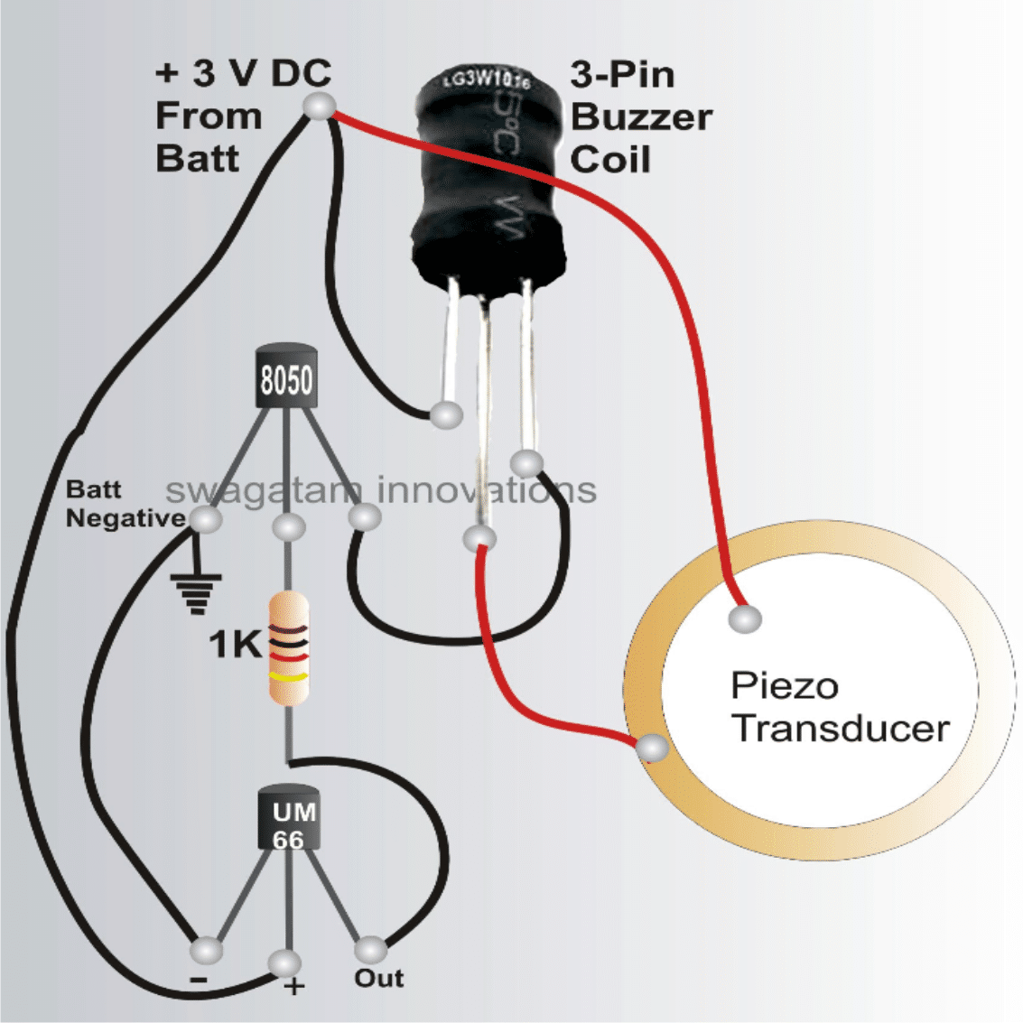
With only a few electrical components needed, the suggested melodic hooter may be built with ease, as shown by the circuit diagram above.
The renowned 8050, a common universal transistor, is the transistor T1. An 8050 can safely take current as high as 150 mA and is substantially stronger than the typical BC547 kinds.
Indeed, the main purpose of the transistor is to increase the audio origin, but it also has the advantage of having higher hFE values than other comparable types of transistors, which leads to more effective music amplification.
This song's inspiration comes from the amazing IC UM66, that has a song "written" into it. To operate, it just requires a supply voltage of 3 V, not more. The pin-outs are also quite easy to comprehend.
It's easy to understand: the left leg represents the negative, the middle leg represents the positive, and the right leg represents the output.
The UM66 begins vocalizing via its output pin as soon as the appropriate supply connections are attached to their pins.
But before sending it to the step-up coil, the sound frequency requires to be boosted because it is extremely low. As previously mentioned, T1 does this, and the amplified signal is then transferred to the coil.
Booster Coil
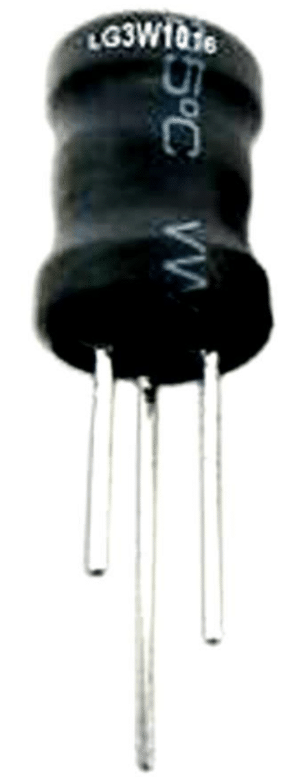
The Role of Buzzer Coil
The purpose of the coil in this instance is to essentially scale up the amplified music variations coming from the transistor T1, acting as a step-up transformer.
Similar to a typical transformer, the coil is divided into primary and secondary portions, but instead of isolating each of them, it winds them as a single coil with the center tap drawn out at the proper, predetermined step.
Using a multi-tester, the matching resistances are measured to determine which winding lead is main and which is secondary.
The primary winding exhibits reduced resistance, whereas the secondary winding has a substantially greater value.
Typically, the secondary area displays a value of approximately 170 ohms, whereas the primary section indicates a value of about 33 ohms. The central tap serves as the common connection between the readings and connects to the positive supply.
Why a Piezo Transducer is used
Direct connection across the secondary winding is made to the piezo dish, which is in charge of actually reproducing music.
Soldering the connection across the center circle requires extreme caution. The piezo's inputs from the core white region and the outside metal edge are both solderable.
From the moment as the solder spot is created, verify that the solder tip is removed; otherwise, the white ceramic coating would burn instantly, decreasing the device's effectiveness.
The Right way to Fix the Piezo Transducer
The installation or fastening technique of the piezo element is an additional factor.

Mounting is carried out atop a plastic plate or cover with a depth of approximately 5 mm and a central raised step encompassing the inner bottom border of the cap, measuring approximately 1.5 mm in height and 1 mm in width (see fig).
The piezo simply rubs within the cap and sits over the raised step because of the inner dimension of the cap. And that's exactly where the piezo is positioned and adhered to within the cap (refer to to illustration).
A high-quality synthetic rubber-based adhesive, similar to that used for adhering leather and rubber, could be employed for the bonding.
The center hole on the reverse side of the cap, which has a predicted dimension of, say, 7 mm, controls how loud the sound produced by the piezo element is.
The degree of crispness and loudness of the audio may be significantly changed by adjusting the hole's diameter.
Two penlight batteries may be used to power the device after the circuit and piezo assembly are fully wired. This will provide the circuit with the necessary three volts.
It's incredible how loud and ear-piercing the tunes may become, especially using such a little power source.
3V is Enough
Nevertheless, as the IC UM66 is unable to endure voltages higher than 3 volts, the supply shouldn't be increased over this amount.
Naturally, the gadget may operate at greater supply voltages—up to 12 volts—but only after the IC's source is monitored and controlled to 3 volts using a zener network and a resistor.
The amplification increases to an extremely powerful level and may even be used as musical reverse horns on automobiles with a 12 volt source.
Parts List for the Bicycle Horn Circuit
All resistors are ¼ watt, CFR, 5 %, unless otherwise stated
- R1, R2 = 1 K = 1
- T1 = 8050,Coil = As shown in the diagram = 1
- COB = UM 66 IC or any other similar type = 1
- Piezo = 27 mm, two terminal type, as shown in the diagram = 1
- PCB = Veroboard or any general purpose PCB = 1