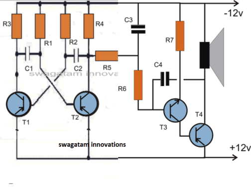
Here is a circuit diagram for a two-tone siren that produces a loud sound with varying frequency. You can use it with any power supply voltage, so it is suitable for cars, motorcycles or homes. It can also serve as an alternative to a regular doorbell.
A dual-tone siren is a circuit that amplifies an alarm sound and switches between two distinct tones. It creates an alternating sound effect similar to a siren.
Circuit Operation
The circuit has an oscillator and two independent multivibrators that run continuously.
An astable multivibrator, also known as a free running multivibrator, is a circuit that has two quasi-stable states and switches between them periodically. The output of each state is coupled to the input of the other through a capacitor.
Because neither state is stable, the output oscillates between high and low levels.
The output consists of low pulses whose frequency is determined by the base biasing resistor and the coupling capacitor.
If the resistors and capacitors for both stages have different values, the output waveform is rectangular. This happens because the time constant of the two quasi-stable states is not the same.
To produce a square wave output, the time constant of the two states of the multivibrator must be equal. This can be achieved by using the same values of components for both states.
The components used in this dual tone siren circuit generate a square wave output with a time constant that creates a smooth rise and fall of the siren sound.
Changing the value of coupling capacitors can achieve any desired time constant.
The oscillator section is the second unit. The tone of the siren depends on the feedback condenser, which is connected at the output.
The pitch of the sound decreases as the value of the condenser increases. For a high-pitched sound (usually used in sirens), a feed-back condenser with a value between 0.047 ufd and 0.1 mfd should be chosen.
The speaker can be either a metallic horn or a small paper cone. The metallic horn produces better results.
The following formula can be used to calculate the transistor astable parts:
T2 = OFF Period of transistor Q1 = ON Period of Transistor Q2 = 0.693R2C2
T1 = OFF Period of transistor Q2 = ON Period of Transistor Q1 = 0.693R1C1

Parts List
- Transistors : BC177 2 Nos.
- BC 107 1No. T 1
- SK100 1No.
- Coudensers : 16 mfd 16 volts 1 No.
- 0.1 mfd 3 Nos.
- Resistances (1/4watt) 2.2 K 2 Nos.
- 22 K 2 Nos.
- 27 K 2 Nos.
- 10 ohm 1No.
- Speaker 8+16 ohm.
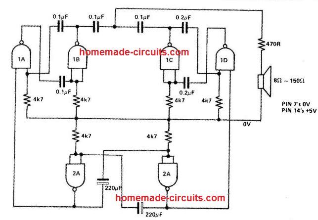
2 Tone Siren Using IC 7400
Applying two oscillators to produce the sounds, the subsequent two-tone siren circuit is constructed.
In order to generate the necessary two-tone sound effect, a third oscillator is included to alternately toggle its counterparts ON and OFF.
To have varied tonal ranges, you can play around with the capacitor's value and adjust it to suit your tastes.

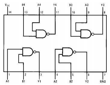
IC 7400 pinout diagram