Have you ever been plunged into darkness by a sudden power outage? Fumbling for candles or tripping over furniture isnt exactly ideal. This guide offers a solution: 10 easy-to-build emergency light circuits using super bright LEDs!
What's an Emergency Light?
Imagine a helpful little light that turn on automatically when the power goes out. Thats an emergency light! It uses a battery to power bright LEDs, keeping you safe and providing light during outages. It' is even more efficient than older lights because it uses LEDs instead of regular bulbs.
Important Safety Note: While some of these circuit are simple to build, it's important to be cautious. A few designs work directly with mains power and should NOT be touched while plugged in. Safety first. If you' are not comfortable working with electronics, it's best to find a pre-built emergency light.
How Emergency Lights Work:
These clever circuits automatically sense when the power goes out and turn on the LED light. When the power comes back on, they turn themselves off. This is especially handy in places with frequent outages, keeping you prepared and helping you navigate until the power is restored. Lets dive deeper and explore how these circuits work!
1) Using a Single PNP Transistor

We all know LEDs need a specific voltage to light up properly. This "sweet spot" voltage lets them operate most efficiently. If you give them more voltage than they need, they waste energy by getting hot. Thats what happens with the extra voltage from a fully charged 6-volt battery in this circuit (LEDs typically need around 3.5 volts).
To fix this, I added a few special diodes in series with the battery. These diodes "eat-up" some of the voltage, dropping it down to the perfect level for the LEDs. Heres, the cool part: as the battery loses power, some of the diodes automatically turn off, letting just the right amount of voltage through to keep the LEDs lit.
By keeping the voltage close to what the LEDs need, this circuit uses less power and last,s much longer during an outage than a regular setup. That mean more light for you when you need it most!
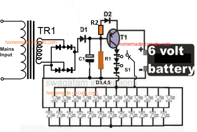
How this White LED Emergency Light Works
This circuit might seem complex at first glance, but let's break it down step-by-step using the diagram [reference the diagram location, e.g., "on the next page"].
The Power Source:
Imagine the transformer, bridge rectifier, and capacitor as a team. They work together to convert the incoming AC power (from your wall ac outlet) into a smooth DC voltage that the circuit can use.
The On/Off Switch (with a twist!):
A single transistor acts like a special switch in this circuit. Unlike most transistors this one (PNP type) turns on when it's base loses connection to positive voltage.
Power On = Lights Off:
When the regular power is on, a positive voltage is applied to the transistor's base, essentially "holding it down" and keeping it off. This prevents the battery from powering the LEDs. Meanwhile the circuit cleverly charges the battery using a trickle charging system.
Power Gone = Lights On!
The moment a power outage strikes, the positive voltage at the transistor's base disappear's. This "release" the transistor, allowing it to turn on. The LEDs instantly light up, powered by the battery.
A Touch of Efficiency:
A neat trick with diodes helps extend battery life. Initially all the diodes are in the circuit, reducing voltage slightly. As the battery weakens, the diodes are gradually bypassed, allowing more voltage to reach the LEDs and keeping them lit for a longer duration.
Parts List
- R1 = 10K,
- R2 = 470 ohms
- C1 = 100uF/25V,
- Bridge diodes and D1, D2 = 1N4007,
- D3---D5 = 1N5408,
- T1 = BD140
- Tr1 = 0-6V, 500mA,
- LEDs = white, hi-efficiency, 5mm,
- S1 = switch with three changeover contacts. Using Transformerless power supply
No transformer? No problem!
While the previous circuit offered great features, it required a transformer. Heres an alternative way to build an automatic emergency light using just LEDs and some common components - all without a transformer!
Benefits of a Transformerless Design:
Ditching the transformer makes this design shine.... The circuit becomes smaller, easier to build, and most importantly, more affordable.
Safety First!
Warning: It's crucial to understand that this circuit is directly connected to the AC mains. This can be extremely dangerous if touched while exposed. If you' are not comfortable working with electronics at this level, it' is best to stick with the transformer-based design or purchase a prebuilt emergency light. Always prioritize safety when working on electrical projects!
Circuit Description
Transformerless Design for Simplicity
This circuit forgoes a traditional transformer, and utilizes a compact power supply built with C1 (capacitor), R1 (resistor), Z1 (surge protector - optional), D1 (diode), and C2 (capacitor).
Operational Breakdown:
- AC Power Present: While AC mains power is available, this mini power supply keeps the PNP transistor (T1) in the OFF state. The AC voltage across its base-emitter junction achieves this. Simultaneously the circuit provides a trickle charge to the connected battery.
- Power Outage Response: The moment a power outage occurs the AC voltage disappears. Without this biasing voltage, the transistor (T1) can no longer be held off. With the help of resistor R2, it transitions to the ON state. This allows current from the battery to flow through T1, illuminating the LEDs.
Battery Options and Considerations:
The diagram uses a 9-volt battery. However a 6-volt battery can also be employed. If using a 6-volt option, you'will need to remove diodes D3 and D4 from the circuit entirely. In their place, insert a wire link to bypass the diodes. This allows the lower voltage from the 6-volt battery to reach the transistor and LEDs directly.
Automatic Emergency Light Circuit Diagram

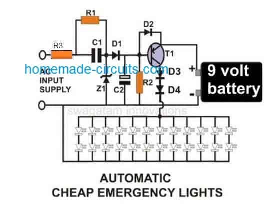
Parts List
- R1 = 1M,
- R2 = 10K,
- R3 = 50 ohm 1/2 watt,
- C1 = 1uF/400V PPC,
- C2 = 470uF/25V,
- D1, D2 = 1N4007,
- D3, D4 = 1N5402,
- Z1 = 12 V/ 1Watt,
- T1 =BD140,
- LEDs, White, High Efficiency, 5mm
PCB Layout for the above circuit (Track side view, Actual Size)

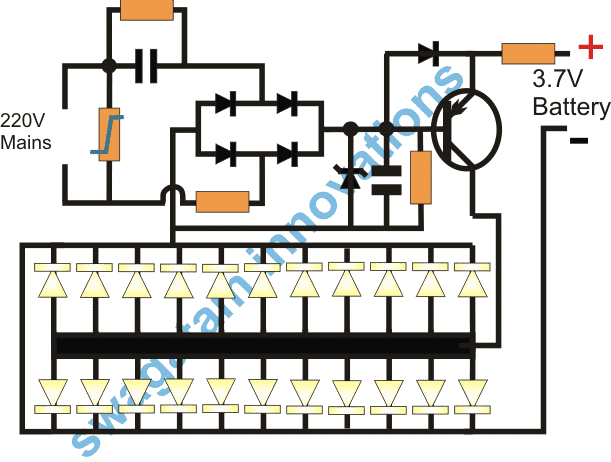
Pats List
- R1 = 1M
- R2 = 10 ohm 1 watt
- R3 = 1K
- R4 = 33 ohm 1 watt
- D1---D5 = 1N4007
- T1 = 8550
- C1 = 474/400V PPC
- C2 = 10uF/25V
- Z1 = 4.7V
- LEDs = 20ma/5mm
- MOV = any standard for 220V application
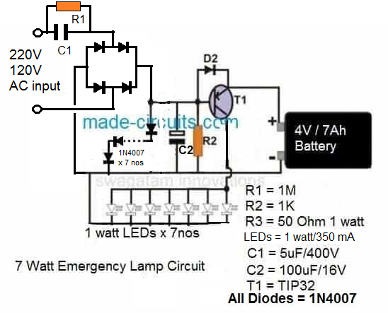
2) Surge Protected Automatic Emergency Lamp
This emergency light circuit incorporates surge-protection for added safety. It achieves this, by using seven diodes connected in series. These diodes are forward biased, meaning they allow current to flow through them in the intended direction. Their position is after the input capacitor in the circuit.
The key benefit of these diode is their voltage drop. When current flows through a diode in forward bias, theres a small voltage drop across the diode itself. In this circuit, with seven diodes in series, the total voltage drop is around 4.9 volts. This effectively "eats-up" some of the incoming voltage, resulting in a more stable and controlled output voltage for charging the connected battery. This stabilized voltage helps to protect the battery from potential surge in the AC mains supply.

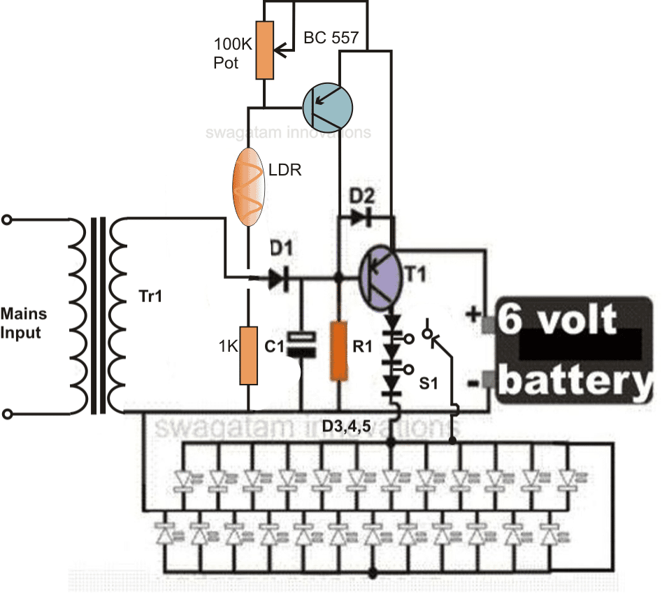
Introducing Day/Night Automatic Activation with LDR!
By popular demand from a reader, we'have taken the previous automatic LED emergency light circuit a step further. This improved design incorporates a second transistor stage with an LDR (Light Dependent Resistor) trigger system.
What's an LDR?
An LDR is a special component that act like a resistor that changes its resistance based on the amount of light it detects.
How it Works: Saving Battery Power by Day
The new LDR stage essentially acts like a smart switch. During the day when theres plenty of ambient light, the LDR detects this and keeps the emergency light off. This helps preserve precious battery power by preventing the light from turning on unnecessarily.
Night-time Activation: Light When You Need It
As darkness falls and the LDR senses the decreasing light levels... it triggers the second transistor stage. This in turn, activates the emergency light, ensuring you have illumination when its truly needed.
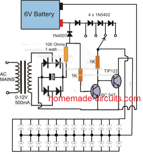
Circuit modifications for operating 150 LEDs.

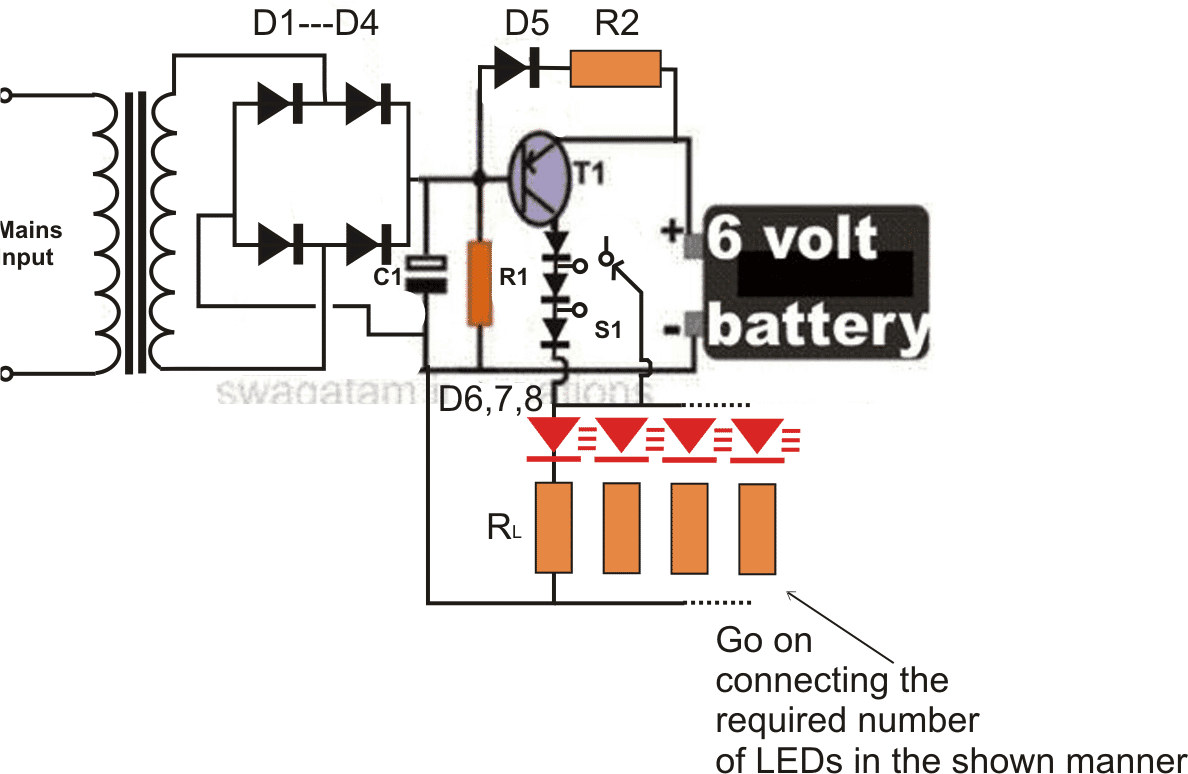
Parts List for the 150 LED emergency light circuit
R1 = 220 Ohms, 1/2 watt
R2 = 100Ohms, 2 watts,
RL = All 22 Ohms, 1/4 watt,
C1 = 100uF/25V,
D1,2,3,4,6,7,8 = 1N5408,
D5 = 1N4007
T1 = AD149, TIP127, TIP2955, TIP32 or similar,
Transformer = 0-6V, 500mA
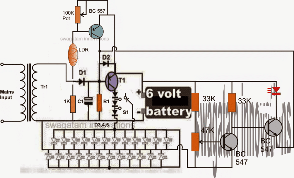
3) Extending Battery Life: Automatic Low-Battery Cut-Off
This circuit takes things a step further, by incorporating a low-voltage cut-off feature. This clever addition helps to protect your battery from over-discharging.

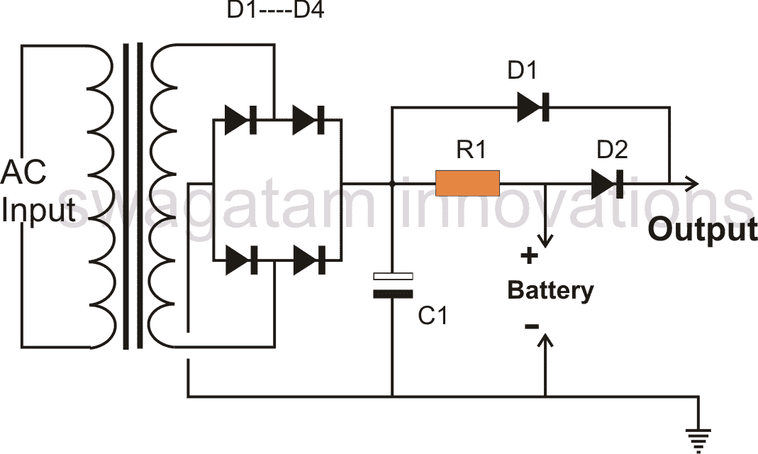
4) Reader Requested: Power Supply with Backup.
This circuit, as requested by a reader acts as a combined power supply and emergency light system. Here's how it works:
- AC Power On: When your AC mains power is available, the circuit does two things:
- Trickle Charges the Battery: A small current (controlled by resistor R1) flows through the battery slowly charging it for later use.
- Provides Main Power (via D1): The circuit uses a diode (D1) to allow the DC output from the transformer to reach your devices (the 'load"). This keeps them powered normally.
- Important Note: While AC power is present the diode D2 is blocked, because of the voltage at D1.
- Power Outage: When a power outage strikes, things change:
- Battery Takes Over (via D2): Since the AC power disappears, the voltage at D1 drops. This allows diode D2 to conduct and instantly supply backup power from the battery to your devices. The transition happens smoothly, with minimal interruption.
Basically this circuit offers a seamless transition from AC power to battery backup during an outage ensuring your devices stay powered.
Parts List for an emergency light back up circuit
All Diodes = 1N5402 for battery up to 20 AH, 1N4007, two in parallel for 10-20 AH battery, and 1N4007 for below 10 AH.
R1 = Charging Volts - Battery volts / charging current
Transformer Current/Charging current = 1/10 * batt AH
C1 = 100uF/25
5) Modifying the above Using NPN transistors
Our first circuit can also be constructed with NPN transistors, as demonstrated here:

6) Reader Challenge: Emergency Light with Relay
This section tackles a readers request for a simple LED emergency light circuit which utilizes a relay for automatic switching between AC power and battery backup.
Circuit Goal is: Seamless Power Transition
The objective here is to create a circuit where:
- During AC power availability, a 12V transformer charges a 12V battery (like a motorcycle battery).
- In the event of a power outage.. the battery seamlessly takes over, powering a 10W LED light.
Reader's Problem: Relay Not Switching Off
The reader encountered a problem where the relay wasnt disconnecting from the AC power when a power outage occurred. They wanted to maintain a very simple circuit design.
Solution: Separate Power Paths for Relay Coil and Light
The solution lies in how the relay is wired. Heres the fix:
- Relay Coil: Connect the relay coil directly to the rectified DC output from the 12-0-12 transformer. This ensures the relay only receives power when AC mains is available.
- Relay Contacts: These contact should solely be connected to the battery and the LED light. This allows the battery to power the LED when the relay switches due to a power outage.
Clarifying the Readers Concern:
The reader expressed concern that if the relay contacts only connect to the battery and LED, how will the battery charge during AC power. This is a valid point! Heres the explanation:
- Even-though the relay contacts are not directly involved in charging the battery, the rectified DC output from the transformer (which powers the relay coil) still provides charging current to the battery through a separate path (likely via a diode). This ensures that the battery gets charged while the relay is activated by AC power.
The Design

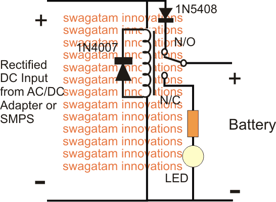
No need for words, If the circuit diagram is clear and well-labeled then you might not need any text at all. Let the diagram speak for itself.
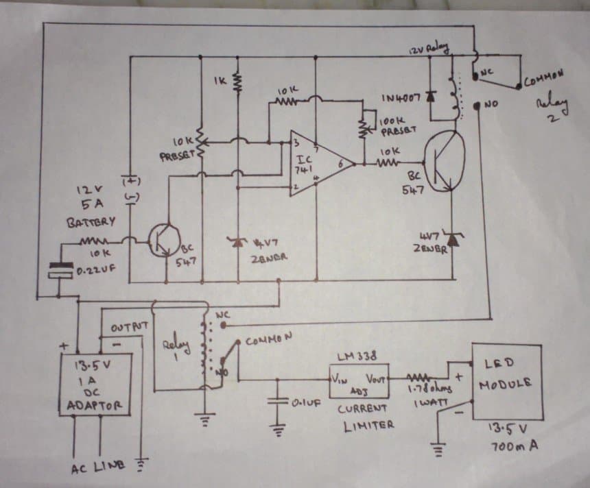
7) Smart Design: Emergency Light & Charger in One with a Single Relay (For Experienced Builders Only)
This entry demonstrates how just a single relay can be utilized to create an emergency lamp with battery charger.

This circuit uses a standard 12V relay with a 400ohm coil resistance. Lets see how it controls the power flow:
AC Power On:
- Relay Activated: When AC power is available, the rectified voltage from a capacitor based power supply energizes the relay coil. This activates the relay connecting its contact to the Normally Open (N/O) terminal.
- Battery Charging: With the relay in this position, the battery charges through these contacts. A 100ohm resistor limits the charging current to a safe level.
- Overcharge Protection: The 4V zener diode acts as a safety measure. If the charging voltage rises very high, the zener diode conducts, preventing the 3.7V battery from over-charging.
Power Outage:
- Relay Deactivates: The moment a power outage happens, the relay coil loses power, causing the relay to deactivate. Its contact shift away from the N/O terminal and connect to the Normally Closed (N/C) terminals.
- Lights On!: With the relay contact switched, the N/C terminals connect the LEDs directly to the battery. The 100 ohm resistor again limits current flow, and the LEDs illuminate, providing emergency light.
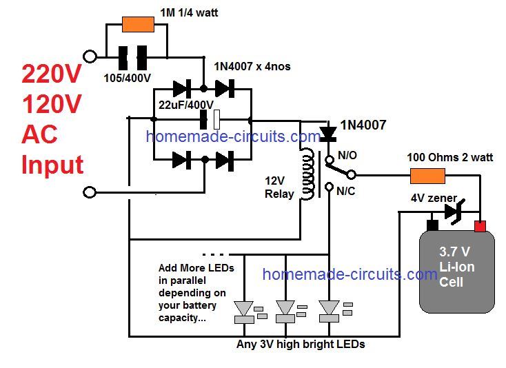
8) Reader Request: Emergency Light with Li-Ion Battery (Built!)
A reader named Dan, requested a circuit design for an emergency light using a Lithium-ion (Li-ion) battery. Heres the solution!
Dan Request:
Dan wanted a circuit that could:
- Charge a 3.7 volt Li-ion battery (potentially from a Nokia phone charger circuit)
- Use the charged battery to power 1 watt LEDs connected in parallel
- Include a light indicator to show charging status
- Automatically switch on the LED during a power outage
The Design:
This circuit diagram fulfills Dan's requirement and can be easily built using the following schematic

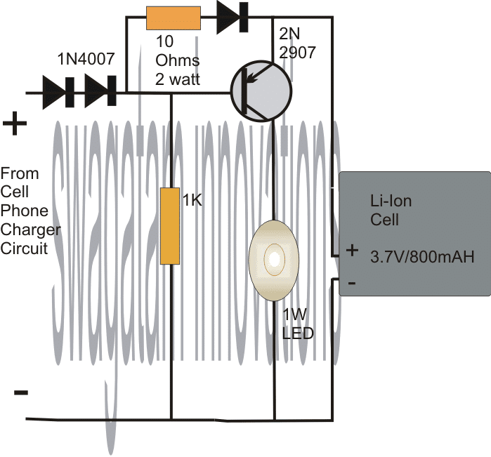
Using a Current Control for the LED

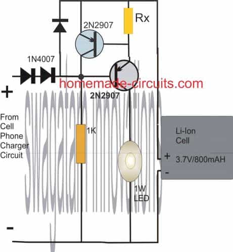
Rx = 0.7 / 0.3 = 2.3 ohm 1/4 watt
Li-ion Battery Charging (Safety First!)
The voltage from the cell phone charger need to be adjusted before connecting it to the Li-ion battery. Heres why:
- Safety Precaution: Li-ion batteries can be damaged by overcharging. To prevent this we need to limit the voltage going to the battery to around 4 volts.
- Simple Voltage Adjustment: This circuit uses diode to reduce the voltage from the charger to approximately 3.9-volts. It's crucial to double-check this voltage with a multimeter before connecting the battery. While this voltage wont fully charge the battery, it prioritizes safety and prevents overcharging.
Automatic Power Switching with Transistor
A PNP transistor controls the power flow:
- AC Power On: When regular AC power is available the transistor remains off (reverse-biased) due to the AC voltage. Meanwhile, the Li-ion battery receives a trickle charge.
- Power Outage: During a power outage, the transistor loses its biasing voltage and turns on thanks to the 1K resistor. This allows the charged battery power to flow through the transistor, illuminating the 1-watt LED.
Important Safety Note:
The following transformerless design is included for informational purposes only. However it's critical to understand the safety risks:
- WARNING: This circuit is directly connected to the AC mains, making it extremely dangerous to touch while exposed. It has also not been thoroughly tested in practice. Only build this circuit if you are a highly skilled electronics professional and prioritize safety measures.
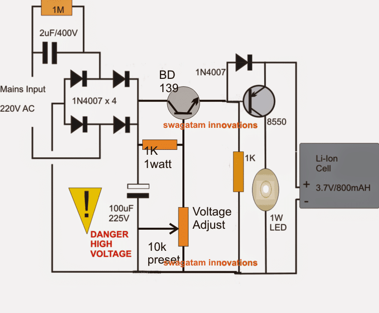
Transformerless Power Supply (Use with Caution!)
This section presents a transformerless power supply circuit for this emergency light. Remember the safety warning above!
Circuit Breakdown:
- Regulated Transformerless Design: This circuit act as a regulated transformerless power supply. It can also function as a 1 watt LED driver circuit.
- Improved Safety: This design aims to addres some of the safety concerns typically associated with transformerless power supplies.
- Capacitive Power Supply Stage: The 2uF capacitor and the 4 x 1N4007 diodes work together to form a basic mains operated capacitive power supply.
Remember, Safety is paramount when working with electronics, especially circuits connected to the AC mains. If you'are not comfortable with the risks involved, it's best to stick with the previously described design using a regulated phone charger or opt for a pre-built emergency light.
Precise Charging with an Emitter Follower
This circuit incorporates a "emitter-follower" stage with additional components to act like a voltage regulator with a preset.
Setting the Charge Level:
- The purpose of this stage is to limit the voltage delivered to the Li-ion battery to a safe level! A preset allows you to adjust this voltage but it's recommended to set it around 4.5 volts for charging.
- Important Note: Due to the presence of a diode (1N4007) in series with the battery, the final voltage reaching the battery will be around 3.9 volts. This voltage keeps the battery safely below its full charge limit and prevents overcharging.
The Transistor as a Smart Switch
The transistor (8550) acts like a smart switch which controls when the LED lights up:
- AC Power On: When regular AC power is available the transistor is switched off (reverse biased) because it receives a direct positive voltage from the circuit. This prevents the LED from turning on while the battery charges.
- Power Outage: During a power outage the transistor loses its biasing voltage and turns on. This allows the charged battery power to flow through the transistor, illuminating the 1 watt LED.
- Automatic LED Control: As soon as AC power returns, the transistor immediately switches off again, turning the LED off.
Safety Through Design:
By limiting the charging voltage and using a control transistor, this circuit helps prevent over-charging and ensures the safe operation of the Li ion battery.

9) Automatic 10 watt to 1000 watt LED Emergency Light Circuit
This circuit offers a powerful automatic emergency light solution with built in safety features. However due to its complexity and connection to the AC mains, it's recommended for experienced builders only who prioritizes safety measures.
Circuit Breakdown:
- Power Supply: A standard transformer, bridge rectifier, and capacitor work together to convert AC mains power to DC voltage.
Dual Relay System:
- Lower Relay (LED Control): This relay is powered by the DC supply and controls the LED.
- AC Power On: When AC power is available this relay stays activated, keeping its Normally Open (N/O) contacts disconnected and the LED off (connected to the Normally Closed - N/C - contacts).
- Power Outage: During a power outage, the relay loses power and its contacts switch. The LED then receives power from the battery, via the N/O contact, lighting up.
- Upper Relay (Battery Management): This relay monitors battery voltage and controls charging.
- Battery Charging: When AC power is on and the battery is discharged, the relay stays off (connected to N/C contacts). This allows rectified DC to reach the battery for charging.
- Battery Full: Once the battery reaches full charge (set by a 10K preset), the relay activates (connected to N/O contacts). This connects the battery to the LED circuit.
High Power Handling:
By using relay with appropriately rated contacts, this circuit can handle a much higher wattage load (over 1000-watts) compared to previous examples.

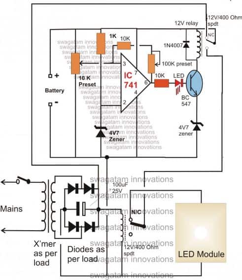
The completed circuit now enhanced with an additional feature, is depicted below:

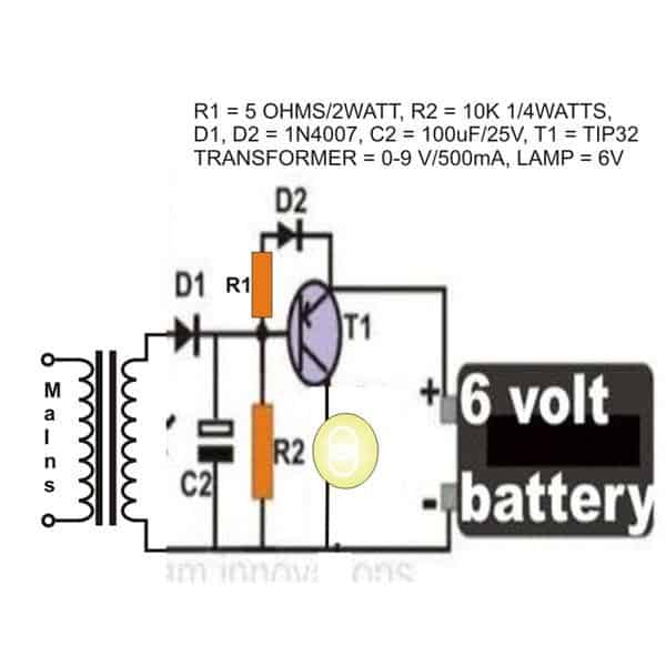
10) Flashlight Bulb Emergency Light
While LEDs dominate the lighting world today, this circuit explores an alternative - a simple emergency light using a classic 3V/6V flashlight bulb. Here's why a flashlight bulb might be a good choice:
- Easier to Set Up: Compared to LEDs, which can have specific voltage requirements and wiring configurations, a flashlight bulb can be a simpler choice for some builders.
Circuit Breakdown (AC Power On):
- Take a look at the circuit diagram, It uses a PNP transistor (T1) as the main switch.
- When regular AC power is available the transistor is positively biased, which keeps it switched off (OFF).
- This prevents battery power from reaching the flashlight bulb, keeping the light off.
- The AC power also charges the connected battery through diode D2 and resistor R1 (which limits the charging current).
Power Outage and Bulb Illumination:
- In the event of a power outage, the transistor (T1) loses its biasing voltage and instantly switches on (forward biased).
- This allows current from the battery to flow through the transistor illuminating the flashlight bulb and providing emergency light.
Practical Implementation:
- You can build this circuit inside a standard AC/DC adapter box. Simply plug it into an existing wall socket.
- Make sure the flashlight bulb protrude outside the box so it can effectively light up the surrounding area.
Remember: Although this design offers a good emergency light, LED technology provides better efficiency, and potentially longer life-spans for the light source.
Parts List
- R1 = 470 Ohms,
- R2 = 1K,
- C2 = 100uF/25V,
- Bulb = Small Flashlight Bulb,
- Battery = 6V, Rechargeable Type,
- Transformer = 0-9V, 500 mA
The Design and Schematic