
A circuit described as the LED AC mains voltage level indicator may be used to monitor and show the current voltage status of any 220 V or 120 V mains household AC input by means of an LED bar graph that rises and falls in accordance with the voltage.
This minimal AC voltage monitor circuit's key characteristics are its straightforward design and precise output. Discover the simplest and most straightforward way to create an LED ac voltage indication.
Importance of Monitoring AC Mains Voltage Level
There may occasionally be harmful swings in the AC mains line that supplies our home's electrical outlets. These might manifest as an abrupt spike in voltage or a drop in voltage.
Both scenarios have the potential to be extremely dangerous for our high-tech electrical devices, which include, but are not limited to, computers, TVs, DVD players, refrigerators, and refrigerators.
The state of this AC mains voltage may be monitored and displayed, and a basic electronic component like an LED can alert us to potential electrical hazards. In this section by building a modest electronic circuit, we will discover the exact method to create an ac voltage indicator with leds.

Construction Hints
It is finished by taking the next few simple steps:
Using the provided circuit diagram as a guide, begin soldering the leads of the transistors and arranging them in a straight line on the acquired general purpose board.
The resistors, zener diodes, LEDs, capacitors, presets, and other components should also be inserted and soldered in an orderly fashion while keeping an eye on the circuit schematic.
Testing Procedure
Additionally, the testing information that follows will assist you in understanding precisely how to create an LED ac voltage indicator:
You will need a transformer that has several voltage outputs in order to test the final circuit board.
It is necessary to connect the transformer to both the AC mains and the negative point of the circuit through the common secondary output of the transformer. Construct a wire/alligator clip assembly.
The clip's wire end should be soldered to the 1N4007 diode input.
Tweak P1 to ensure the first LED just begins to illuminate, then hook the clip to the transformer's 3 volt output.
Continue attaching the clip to the transformer's 6, 7.5, 9 and 12 volts as before, and then play with the settings P2, P3, P4 and P5. This should cause the required LEDs to just begin to glow at the appropriate voltages. This ends the circuit's testing and configuration.
Lastly, connect the circuit to the 6 volt transformer and turn on the supply of power. LEDs 1, 2, and 3 will all be brightly lighting.
While the very last LED is fully off, LED number four is flashing with reduced brightness, signifying an appropriate level of AC mains voltage.
The last LED will now begin to illuminate intensely in the event that the voltage rises to a high level (over 260 volts), signaling a potentially dangerous scenario.
LED 3 and maybe LED 2 may stop glowing if the voltage falls to a hazardous level (below 160 V), once more signaling a problematic low voltage.
Parts Required
- The parts listed below are required for the project:
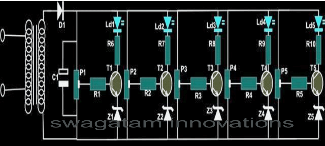
- TRANSISTORS T1, 2, 3, 4, 5 = BC547
- ZENER DIODE Z1----Z5 = 3 VOLTS / 400mW
- RESISTORS R 1—R10 = 1 K ¼ WATT, CFR.
- CAPACITOR C1 = 1000uF/25v,
- DIODE D1 = 1N4007
- LED 1, 2, 3, 4, 5 = RED 5mm DIFFUSED
- PRESET P1, 2, 3, 4, 5 = 47K LINEAR
- GENERAL PURPOSE BOARD = 6” x 2”
- TRANSFORMER = O – 6 VOLTS/ 500mA
AC Mains Level Indicator Circuit using LM358 IC
It's helpful to know, even without seeing, if the AC voltage level is low, particularly if you're going to be using a computer.
However, there is a risk involved. Additional loads might push the AC voltage to drop much lower than acceptable limits if the mains is already low.


The proposed circuit's source comes straight from the mains, which are connected across R1 and P1.
The 15 V steady-state voltage produced by R2, C1, C2, D1, and D2 provides two benchmark voltages.
Both of these voltages are evaluated in A1 and A2 from the IC LM358 using a predetermined reference level of the mains voltage. D7 will glow if the voltage drops below 210 V for the following mains. The illumination on D8 will turn on once the reading exceeds 250 V.
T1 switches on and permits D4 to be illuminated if none of them illuminates. All that indicates is that the mains voltage is within safe working parameters.
Setting up the Presets
With the use of a variac and a voltmeter, Preset P1 determines the AC voltage threshold. Any value inside the center of P1's rotation range is acceptable, so you don't need to aim for precision.
It is necessary for the circuit under consideration to be disconnected from the mains. We kindly ask you to make sure that this circuit is always isolated from the mains by using a separated fiber case before turning it on.
AC Voltage Monitor Circuit using IC LM324

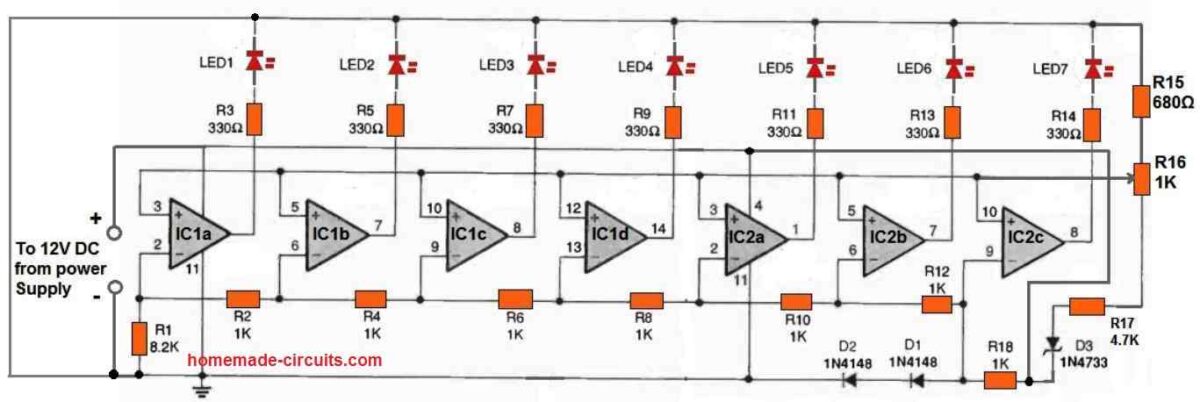
The accompanying picture depicts the circuit architecture for the AC Line-Voltage Monitor. As was already mentioned, a wall transformer with a 12 volt DC rating powers the circuit.
The core of the circuit consists of two quad LM324 op-amp integrated circuits (IC1 and IC2). It is powered by regulated power from a fixed DC source that is provided by a 5.1-volt Zener diode, D3. An LED bargraph is powered by the IC LM324 Op-amps utilizing LEDs 1 through 7.
A configurable reference voltage is supplied to the op-amps via the rotary arm of potentiometer R16.
The voltage divider made up of resistors R1, R2, R4, R6, R8, R10, R12, and R18 provides the input voltage.
These resistor values were selected such that when the AC line voltage, or a tenth of it, fluctuates from 100 to 132 volts, the op-amp outputs switch on consecutively and illuminate the LEDs.
The LED bargraph's midway is typically set by potentiometer R16 at 118 volts, however this value can be changed as desired.