
Power surges, those sudden spikes in voltage, can be a real headache for our electronics. But dont worry we can learn how to build a basic surge protector circuit to offer some protection!
What is a surge protector?
A surge protector is a device, that safeguards your electronics from these harmful voltage spikes and other temporary fluctuations that can creep in through your power lines. It acts like a shield for your sensitive equipment.
How does it work?
Surge protectors work by diverting any excess voltage that might appear on the power line for a very short time (usually just microseconds). This quick action prevents the high voltage from reaching your electronics and potentially damaging them. However if the surge lasts longer, the surge protector itself might take the hit and burn out.
Voltage spikes: The enemy of electronics
A voltage spike is a brief but powerful surge in voltage that can last just milliseconds. Despite their short duration, these spikes can easily damage delicate electronic components. Thats why it's important to find ways to stop them from reaching your devices.
Are store-bought surge protectors reliable?
While commercially available surge protectors are affordable and easy to find, some might not be very reliable. They might not have undergone rigorous testing, leaving you unsure of their actual effectiveness. Building your own basic surge protector can be a good alternative, but remember, safety is paramount!
Basic Design
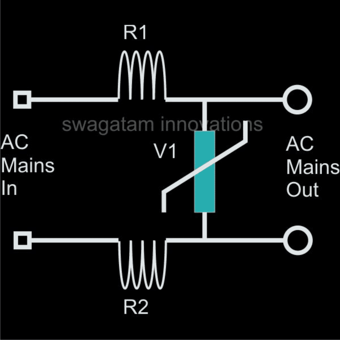
This circuit explains a basic AC mains surge protector. It uses a simple approach, to absorb sudden spikes in voltage.
Common resistors and a MOV (Metal Oxide Varistor) are all that's needed for this protection. In the circuit R1 and R2 are made by wrapping iron wire (0.2mm thick) five times around separate air cores (each 1 inch in diameter). These resistors are then connected in parallel with MOVs to create a complete surge protector.
When a high voltage surge hits the device it's effectively handled by the resistors and MOVs. These components absorb the spike's energy allowing safe and normal voltage to reach your electronics.
Understanding MOV Energy Absorption
This section explains how to calculate the energy absorbed by a Metal Oxide Varistor (MOV) during a surge event.
The Formula:
We use the following formula to estimate the energy (E) absorbed by the MOV:
E = (Vpeak x Ipeak) x t² x K
Where:
- E = Energy absorbed by the MOV (in Joules)
- Vpeak = Peak voltage across the MOV during the surge (in Volts)
- Ipeak = Peak current flowing through the MOV during the surge (in Amps)
- t = Duration of the surge pulse (in seconds, squared in the formula)
- K = Constant dependent on the pulse duration (t)
Understanding the Variables:
- Peak Current (Ipeak) and Peak Voltage (Vpeak): These represent the highest current, and voltage values experienced by the MOV during the surge.
- Pulse Duration (t): This refers to the length of time the surge voltage is present.
- Constant (K): This value depends on the specific pulse duration and is usually provided by the MOV manufacturer's datasheet. A lower K value indicates the MOV absorbs less energy for the same voltage and current.
In simpler terms:
The formula considers the peak voltage, peak current, and surge duration to estimate how much energy the MOV can handle. A lower value of beta (β) which is related to the current level translates to a lower peak voltage and consequently lower energy absorption by the MOV.
Transient Protector Using Inductors and MOV

A Problem Concerning Surge Prevention in Electronic Ballast
I came across your contact information on your blog and I'm hoping you might be able to assist me with a technical challenge I'm facing.
I work for a company that manufactures UV lamps with electronic ballasts for customers in China. Unfortunately, we've been encountering issues with ballast burnout due to voltage fluctuations in the region.
The Remedy
That's an interesting point. It's possible that sudden voltage surges rather than overall fluctuations, could be the culprit behind the ballast failures.
The circuit you provided might not be fully addressing the issue because it lacks components like resistors or surge suppression barriers for the MOVs (Metal Oxide Varistors).
To potentially improve protection I recommend considering this alternative circuit. It can be introduced at the beginning of your existing ballast circuit for better surge protection.
Hope it works:

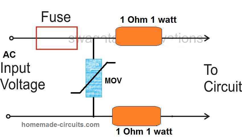
Enhancing Surge Protection with NTC and MOV
This diagram illustrates how combining two surge protection devices, a Negative Temperature Coefficient (NTC) thermistor and a Metal Oxide Varistor (MOV), can provide comprehensive protection for your circuit.
The NTC acts as the first line of defense against inrush current. When initially powered on, the NTC has a high resistance, due to its low temperature. This limits the initial surge of current flowing to the connected device. As the NTC warms up during normal operation its resistance decreases, allowing the full operating current to pass through.
The MOV serves as a secondary protection mechanism. If a high voltage surge overwhelms the NTC's ability to limit current, the MOV activates. By diverting the excess voltage to ground, the MOV safeguards the connected device from potential damage.
This combined approach offers a "double-edged" safety net, ensuring your circuit is protected from both inrush current and transient voltage spikes.


Circuit for Integrated RFI Suppression and Voltage Surge Protection
Looking for a one-stop shop for clean and reliable power? This circuit integrates both RFI filtering and surge protection to safeguard your equipment from unwanted noise and damaging voltage spikes.

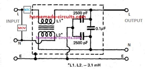
Dual-Stage Protection:
The circuit employs a two-stage protection approach, to safeguard against both voltage surges and radio frequency interference (RFI).
- Stage 1: Surge Protection
- An NTC thermistor provides initial protection against inrush current surges. Its high resistance when cold limits the initial current flow. As the circuit warms up the NTC's resistance decreases, allowing normal operating current.
- An MOV (Metal Oxide Varistor) acts as secondary protection for high voltage surges. If a surge overwhelms the NTC, the MOV activates, diverting excess voltage to ground and protecting the circuit.
- Stage 2: RFI Filtering
- A small ferrite transformer helps suppress incoming and outgoing RFI on the line. Its windings, with one end connection swapped between input and output neutral lines, create a high impedance for these high-frequency signals.
- A network of capacitors complements the transformer, by shunting any residual high-frequency currents to ground, further attenuating RFI.
This two-stage approach ensures that, the circuit is protected from both transient voltage spikes and unwanted radio frequency noise.