
In this article you’ll discover how to construct a very basic buzzer circuit using a piezo electric transducer, two resistors, a small coil, and a BC547 transistor.
A buzzer is a high frequency oscillator circuit designed to produce a buzzing sound via a transducer or speaker output.
Simple Buzzer using a Single Transistor
With just a single transistor, a ferrite inductor, and a piezo transducer, you can create a circuit that will “buzz” or, more accurately, “tweet” for you, potentially producing a sound thats quite loud and ear-piercing.
The straightforward piezo buzzer circuit outlined here operates in a rather distinctive manner. Unlike other oscillators which rely on resistor and capacitor networks to generate oscillations, this circuit utilizes inductive feedback for its operations.
1of30Show learn more suggestions

How the Circuit works
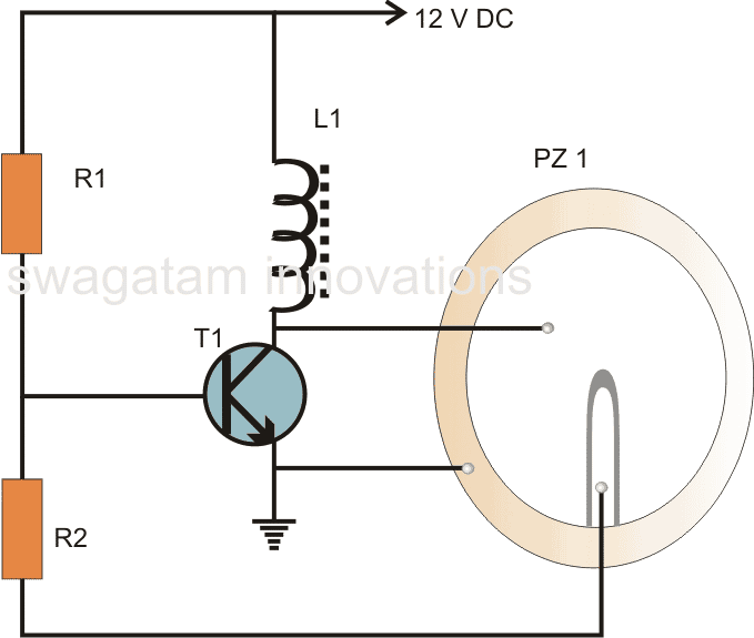
Looking at the buzzer circuit diagram, you will see that the transistor T1 and the inductor are the core component of the circuit.
The coil often referred to as the buzzer coil, is crucially placed to amplify the oscillations, and the actual feedback is provided by the center tap of the three-terminal piezo element that’s used in this setup.
When you supply a voltage into the circuit, the transistor activates, driving the piezo element across the buzzer coil.
The action also grounds the base of the transistor via the center tap of the piezo element, that immediately turns off the transistor, and then, the piezo element also deactivates, freeing the base of the transistor.
The transistor then returns to its initial state, and this cycle repeats, creating the oscillations or the “buzzing” frequency you are looking for.
The center tap of the piezo transducer is crucial in maintaining the oscillations, that is why, for this design, a three terminal piezo is necessary instead of a two-terminal one.
The oscillations generated at the collector of the transistor are transferred into the coil, filling the coil with magnetic inductions.
The coil then returns the stored energy during the oscillations, enhancing the generated AC across it.
This amplified AC is then applied to the anode and cathode of the piezo element causing it to vibrate sharply in tune with the frequencys pitch, producing a sharp, high-pitched sound.
However to ensure the sound is heard at its maximum intensity, the piezo transducer must be fixed or mounted in a specific manner within its housing.
Frequency of Oscillator
Regarding the oscillators frequency, while pin-pointing the precise formula for this circuit might not be possible, the design resembles to a Crystal oscillator where the piezo functions similarly to a ceramic crystal.
Frequency = 1 / 1 / 2π√LSCS
Where Ls and Cs are the internal inductance and capacitance of the piezo respectively.
How to Stick Piezo

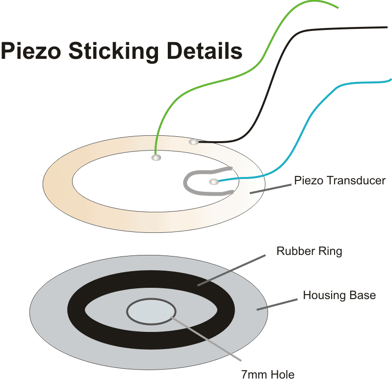
For your project you need to attach the piezo element at the bottom of its case, which should have a hole about 7 mm wide.
Dont stick the piezo element flat on the bottom, instead, place it on a soft, pure rubber ring thats a bit smaller than the piezo about 30% smaller.
If you follow these steps to fix everything in place, your buzzer will work and make noise. If not done this way, the sound might not come out right.
Parts List
- R1 = 100K,
- R2 = 4k7,
- T1 = BC547,
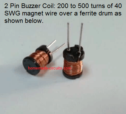
- L1 = Buzzer inductor,

- PZ1 = Piezo element, 27mm, three terminal
- Rubber ring = 22mm