
This article dives into a straightforward circuit designed to safeguard your appliances from voltage fluctuations. Imagine a knight protecting your electronics – that's what this voltage stabilizer does!
How it Works:
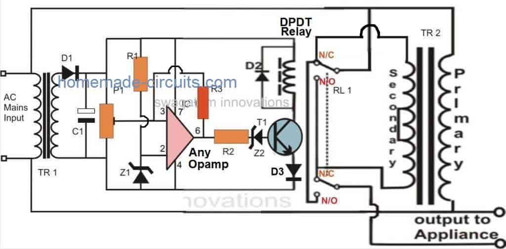
The circuit uses a common operational amplifier (op-amp) chip, the IC 741, as its brain. This chip acts like a voltage comparator, constantly checking the incoming AC voltage from your mains supply.
- A reference voltage, set by a resistor (R1) and a zener diode, is constantly fed to one input of the op-amp (pin 2).
- The other input (pin 3) receives a sample of the actual AC voltage from the transformer.
Think of these inputs like a seesaw. The reference voltage is one side, and the actual voltage is the other. The op-amp keeps them balanced.
- A special control knob (preset) lets you adjust the balance point. This determines the voltage level that the circuit considers "dangerous" for your appliances. We'll cover setting this point later.
When the actual voltage (pin 3) gets too high or too low compared to the reference, the op-amp reacts:
- If the voltage gets too high, the op-amp's output (pin 6) flips to "high." This activates a transistor and a special relay.
- The relay is a double-throw type, like a switch with two outputs. It's connected to a modified transformer with multiple voltage taps.
By strategically switching these taps, the transformer can either boost or decrease the voltage going to your appliances:
- If the voltage is too high, the relay adjusts the transformer to "subtract" some voltage, keeping it safe for your electronics.
- If the voltage is too low, the transformer can be adjusted to "add" some voltage, ensuring your appliances get the power they need.
In essence, this circuit acts like a guard, constantly monitoring and adjusting the voltage to keep your electronics safe from harmful fluctuations.
Complete Circuit Diagram

Setting the Reference Voltage (Optional):
The circuit we discussed uses a zener diode to create a stable reference voltage. However, you can also achieve this using a resistor voltage divider. This is a network of two resistors that splits the supply voltage (Vcc) into a specific voltage level.
If you choose to use a resistor divider instead, here's the formula to calculate the reference voltage (Vref):
Vref = (R2 / (R1 + R2)) x Vcc
- Vref: Reference voltage you want to create (usually a fixed voltage)
- R1: Resistance of the first resistor in the divider circuit
- R2: Resistance of the second resistor in the divider circuit
- Vcc: Supply voltage of the circuit
Benefits of a Resistor Divider:
- More precise control: Resistor values can be chosen very accurately, potentially leading to a more stable reference voltage compared to a zener diode.
- Cost-effective: Resistors are generally less expensive than zener diodes.
Drawbacks of a Resistor Divider:
- Temperature dependence: The resistance of resistors can vary slightly with temperature, which could cause minor fluctuations in the reference voltage.
Choosing the Right Method:
The choice between a zener diode and a resistor divider depends on your specific needs. If precise voltage control is critical, a resistor divider might be a better option. If simplicity and cost are your priorities, a zener diode is a good choice.
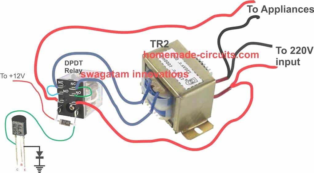
Transformer Relay Wiring Diagram

Parts List
You will require the following components to make this homemade automatic mains voltage stabilizer circuit:
- R1, R2 = 10K,
- R3 = 470K or 1M, (lower values will enable slower voltage corrections)
- C1 = 1000 uF / 25 V
- D1, D2, D3 = 1N4007,
- T1 = BC547,
- TR1 = 0 – 12 V, 500 mA,
- TR2 = 9 – 0 – 9 V, 5 Amp,
- IC1 = 741,
- Z1, Z2 = 4.7V/400mW
- Relay = DPDT, 12 V, 200 or more Ohms,
- Approximate Voltage Outputs for the Given Inputs
Stabilized Output Vs UnStabilized Input Voltage Proportions
INPUT------OUTPUT
200V -------- 212V
210V -------- 222V
220V -------- 232V
225V -------- 237V
230V -------- 218V
240V -------- 228V
250V -------- 238V
Calibrating Your Voltage Stabilizer (Important!)
Before connecting your circuit to the mains power, follow these steps to calibrate it for optimal performance:
Prepare for Calibration:
- Disconnect both transformers from the circuit.
- Locate resistor R3 and leave it disconnected for now.
Power Up with a Safe Supply:
- Use a variable power supply (not mains power!) to provide temporary power to the circuit. Connect the positive output of the supply to pin 7 of the op-amp (IC) and the negative output to pin 4.
Set the Reference Voltage:
- Adjust the variable power supply to output around 12.5 volts.
- Use the preset resistor to fine-tune the voltage until the op-amp's output (pin 6) triggers the relay "on."
Important Note: The 12.5V reference point might differ slightly for your specific circuit. Here's what to do:
* **Measure Your Threshold:**  Before proceeding, find the DC voltage output from transistor TR1 that corresponds to a desired AC input voltage from your mains (e.g., 225V AC). Let's call this measured voltage "V_TR1."
* **Adjust the Calibration:**  During calibration, use V_TR1 instead of 12.5V. So, if V_TR1 is 13V for 225V AC input, use 13V during calibration.
Verify Relay Operation:
- Slowly decrease the voltage from the variable power supply to around 12 volts. The relay should deactivate (turn off).
- Increase the voltage back to V_TR1 (or 12.5V if you didn't measure). The relay should reactivate (turn on).
- Repeat this process a few times to ensure the relay flips reliably between on and off states.
Calibration Complete!
- You've successfully calibrated the circuit.
Connect to Mains Power (with Caution):
- Now you can connect both transformers to their designated positions in the circuit.
- Reconnect resistor R3 and the relay wires to their original spots.
Safety Precautions:
- Building and using this circuit involves working with mains electricity. Always prioritize safety!
- To minimize risks:
- Use a 100-watt incandescent bulb in series with one of the mains lines going to the transformer during initial testing only. Once everything functions correctly, remove the bulb.
- The entire circuit is not isolated from the mains. Never touch the circuit while it's powered on and exposed. This can cause serious injury or death.
Additional Notes:
- This setup procedure ensures the output voltage to your appliances stays between 200 and 250 volts, even with mains fluctuations ranging from 180 to 265 volts.
- If you're not comfortable with electronics or electrical safety, consider purchasing a pre-built voltage stabilizer for your appliances.
By following these steps carefully and prioritizing safety, you can calibrate and use your homemade voltage stabilizer circuit.