
The design we’ are talking about can be made with the IC 4017 chip and some logic gates, as shown in the diagram.
Mr. Robert asked for help with this fourth circuit.
And heres what he needs:
I’ve just found this website with its circuit designs and I’ am hoping you can help me.
I have a similar need. I’m looking for a circuit that will prevent my submersible water pump, which is 1100 watts, from running when there’s no water left.
I want the pump to turn off when the water level is about 1 meter above where the water goes into the pump, and to turn back on when the water level is about 3 meters above that point.
The pump is connected to the ground which should serve as a common point of reference. There are already probes and wires running up from the pump to the surface at these levels.
I would really appreciate any help you can give. I can build circuits, but I dont really know how to design them. Thanks a lot, I’m looking forward to your guidance.

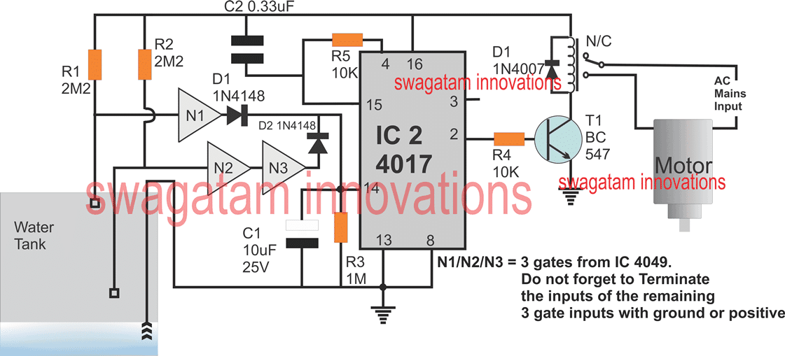
How the Circuit Works
Lets picture the setup as it’s shown in the figure. The circuit starts in the position shown.
We see three sensors in the tank: one is at the bottom, always touching the water. The second sensor is about 1 meter from the bottom, and the top sensor is 3 meters up.
Initially both the top and middle sensors are positively charged through their resistors, making N3’s output positive and N1’s negative.
These outputs connect to pin 14 of the IC 4017, a chip that creates a sequence of signals for this system.
When you first turn on the power, N3’s positive signal doesn’t change the sequence because the IC resets through C2, and the sequence stays on pin 3.
Imagine the tank starts filling with water. When it touches the middle sensor, N3 goes negative, but this doesnt affect the IC.
Once the water reaches the top sensor, N1 becomes positive. This changes the IC’s sequence from pin 3 to pin 2.
Pin 2 connects to a relay that turns on the motor pump. The pump then starts to drain the tank. It keeps going even when the water level drops below the top sensor because this doesn’t change the IC’s sequence.
The pump stops only when the water level falls below the middle sensor. N3 turns positive, shifting the IC from pin 2 to pin 4, which resets it to pin 3.
The pump stays off until the tank fills up again and the water reaches the top sensor.