
This design uses the reliable IC 555 chip to manage the water level in a way thats both straightforward and efficient.

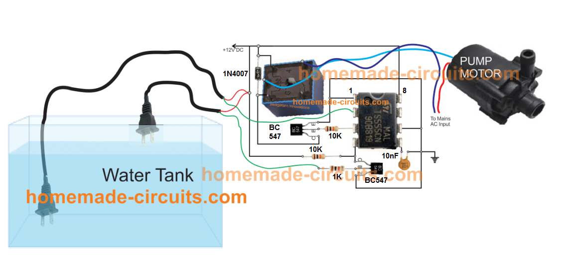

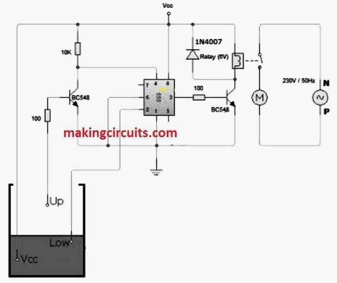
Lets break down how the IC 555 circuit controls the water level in simple terms:
The IC 555 chip has a special pin (pin#2) which when the voltage drops below a certain level (1/3rd of the supply voltage), it makes another pin (pin#3) become active with the full supply voltage.
Pin#2 is placed at the bottom of the water tank to detect when the water is too low.
If the water covers the sensor (a 2-pin plug), pin#2 stays at the full voltage level, keeping pin#3 inactive.
When the water level falls and uncovers the sensor, pin#2 loses its voltage.
This drop makes pin#3 active which turns on a relay.
This relay is like a switch that starts the water pump, filling the tank. Even when the water rises and covers the lower sensor again, the IC 555 doesnt stop right away because of its built in delay (hysteresis).
The water keeps rising until it touches a second sensor at the top.
When this happens it activates another part of the circuit (a BC547 transistor connected to pin#4) which resets the IC 555.
This turns off pin#3, the relay and the water pump. The system then goes back to waiting for the water to drop again, starting the whole process over when needed.