
The idea below details how to construct an electronic ballast circuit that is both straightforward and incredibly dependable, capable of powering a couple of 40-watt fluorescent lights with active power adjustment.
Courtesy: https://www.irf.com/technical-info/appnotes/an-995a.pdf
Key Electrical Characteristics of the IC
Using ground input wires as a reference, International Rectifier Control ICs are monolithic power integrated circuits that may be used to operate both high- and low-side MOSFETs or lGBTs at a logic level.
Unlike typical driver transformers, they have balanced out voltage functionality up to 600 VDC and can provide highly precise waveforms with almost any duty cycle from 0% to 99%.
In addition to the features listed above, the IR215X sequence is a relatively new addition to the Control IC family. It uses a top end that is functionally similar to the LM 555 timer IC.
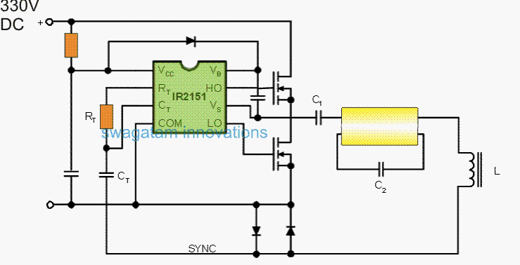
With the use of substitute RT and CT components, such driver chips enable an engineer to create self-oscillating or synchronized vacillation characteristics. View the figure below.

Parts List
| Component | Value | Tolerance | Power Rating | Type |
|---|---|---|---|---|
| Ct | Same as diagram | - | - | - |
| Rt | Same as diagram | - | - | - |
| Lower Diodes | BA159 | - | - | - |
| Mosfets | As recommended | - | - | - |
| C1 | 1 μF / 400V | - | - | PPC |
| C2 | 0.01 μF / 630V | - | - | PPC |
| L1 | As recommended, may need experimentation | - | - | - |
Additionally, they have built-in circuitry that can switch between high and low side components to drive half-bridge power devices and gives a reasonable dead time of 1.2 microseconds between outputs.
Oscillator Frequency Calculation
The frequency of oscillation is easily estimated anytime it is a part of the self oscillatory configuration by:
f = 1/1.4 x (Rt + 75ohm) x Ct
IR2151, IR2152, and IR2155 are the three self-oscillating devices that are available. With tr = 80 ns and tf = 40 ns, the IR2155 appears to include greater durability output buffers that can flip a 1000 pF capacitive load.
It comes with a 150 ohm RT supply and very low power startup. With tr and tf of 100 ns and 50 ns, respectively, IR2151 functions similarly to IR2l55.
IR2152 will continue to be identical to IR2151, despite having a phase shift from red to green. 75 ohm Rt source is included in IR2151 and 2152 (Equation 1.)
These ballast drivers are designed for restricted quiescent current and typically come with a built-in l5V shunt regulator to guarantee that a single limiting resistor operates optimally by means of the DC rectified bus voltage. These ballast drivers usually have the purpose to be supplied with the rectified AC input voltage.
Setting up the network for Zero Crossing
Take another look at Figure 2 and note the driver's capacity for synchronization. An effective zero crossing detector for the lamp current is created by connecting the two consecutive diodes in series with the lamp circuit. L, C1, and C2 are all in a particular string in the resonant circuit immediately before the light strike.
For the resonant circuit to properly be L and C2, C1 is a DC blocking capacitor with a low reactance. The Q factor of L and C2 during resonance increases the voltage surrounding C2, which then strikes the light.
The Process of Determining the Resonant Frequency
The lamp voltage drop promptly short circuits C upon lamp ignition, and L and C1 establish the frequency of the resonant circuit at this juncture.
In the normal process of normal operations, this results in a transition to a lower resonant frequency, which is once again regulated by detecting the AC current's zero-crossing and using the voltage that results to control the driving oscillator.
besides contributing to the driver quiescent current, the DC supply current has a few more components that are features of the application circuit itself:
Assessing Charge Discharge and Current Characteristics
The current flowing from the power FETs' input capacitance being charged
The current generated by the International Rectifier gate driver devices' junction isolation capacitance's charging and discharging. Because each component of the current arc is charge-related, abide by the following guidelines:
- Q = CV
This readily leads to the observation that, in order to charge and discharge the power device's input capacitances, the predicted charge could be found by multiplying the gate drive voltage by the actual input capacitances, and the suggested input power would be precisely equivalent to the product of charge, frequency, and voltage squared:
- Power = QV^2 x F / f
When creating a true ballast circuit, the following considerations are suggested by the aforementioned relationships:
1) choose the lowest operating frequency based on the inductor's decreasing size;
2) use the smallest device volume possible for trustworthy power devices with lower conduction losses (which reduces the charge parameters);
3) DC bus voltage is often used; if another option is available, utilize the lowest voltage.
PLEASE NOTE: Charge is not really a switching rate feature at all. Regarding transition durations of 10 microseconds or 10 ns, the charge communicated is exactly identical.
Now that we have the self-oscillating drivers, we are going to investigate some practical ballast circuits. The so-called "Double 40" kind of fluorescent light fixture, that frequently uses two standard T12 or TS bulbs inside a common reflector, is perhaps the most popular model.
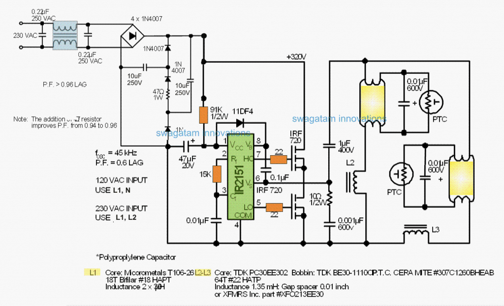
Two suggested ballast circuits are shown in the accompanying figures. The initial circuit is the minimum power factor circuit; the second uses unique diode/capacitor combinations to achieve a power factor greater than 0.95. A standard DC bus of 320 VDC can be produced using the reduced power factor circuit shown in Figure 3 by accepting 115 VAC or 230 VAC 50/60/400 Hz inputs.
Twin 40 Watt Ballast Circuit Diagram

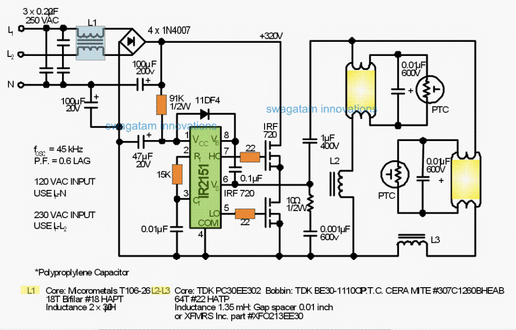

Assuming a non-sinusoidal current wave-form and an input power factor of approximately 0.6, the input rectifiers operate somewhat near the peak values of the AC input voltage.
Other than evaluation circuits and low-power compact fluorescent lights, this kind of rectifier is not recommended at all. It could also turn undesirable should power quality obstacles also lower harmonic currents in power supply devices.
Only during Operation Does the IC Use a Limiting Resistor
The International Rectifier IR2151 Control IC operates directly off the DC bus via a limiting resistor, as can be observed, and adjusts at around 45 kHz in accordance with the relationship stated below:
- f = 1/1.4 x (Rt + 75ohm) x Ct
When V5 (lead 6) gets pulled low inside the low side power switch conduction, a bootstrap capacitor of 0.1 pF provides power for the high side switch gate drive. This capacitor is charged to about 14V.
The moment the high side change executes, the bootstrap diode IDF4 stops the DC bus voltage.
To ensure that the bootstrap capacitor won't be considerably depleted when the diode returns and blocks the high voltage bus, a rapid recovery diode (<100 ns) is required.
In reality, the half-bridge's high frequency output is a square wave with incredibly short transition periods (approximate 50 ns).
In order to reduce the switching durations to around 0.5 ps, a 0.5W snubber with 10 ohm and 0.001 pF is used to prevent aberrant protracted sounds through the rapid waveforms.
Includes an integrated dead time function.
Note that the IR2151 driver has an embedded dead time of 1.2 ps to prevent shoot-through currents in the half-bridge.
The 40-watt fluorescent bulbs are regulated in tandem, each with an independent L-C resonant circuit.
One set of two MOSFETs, adjusted according to the power level, might power about four tube circuits.
The reactance values for the lamp circuit are obtained using L-C reactance tables or by applying the following equation for series resonance:
- f = 1/2pi x square-root of LC
The Q of light circuits is quite minimal since they enjoy the benefits of operating at a constant rate of recurrence, that may vary according to RT and CT limitations.
The fluorescent bulbs do not normally require particularly high striking voltages, therefore a Q of 2 or 3 is sufficient. 'Flat Q' curves frequently result from larger inductors and low capacitor ratios, in where
Q = 2pi x fL / R, whereby R is frequently higher since numerous additional turns are used.
Using PTC thermistors surrounding each lamp can prevent soft-starting throughout tube filament pre-heating at a low cost.
As a result, the voltage throughout the lamp continuously increases as the RTC self-heats finally the striking voltage combined with hot filaments is obtained and the light fires up.