Traditional candles can be replaced with a flameless option thanks to this circuit. It produces a realistic candle-like glow by using easily accessible electronic parts like LEDs and batteries.
The ability to blow out the light with a puff of air, just like you would with a real candle, is a unique feature.
Advantages and Things to Think About:
Safety: Removes the possibility of fire that comes with using regular candles.
Durability: Prolongs lifespan and prevents meltdowns of wax.
Interactivity: Provides a fun way to turn on and off the light.
For those who are interested in electronics or are just hobbyists, building this electronic candle circuit can be entertaining and educational.
How the Circuit Works
Caution: High Voltage Circuit
Working with AC mains electricity is a requirement for this project, and if safety precautions are not taken, it could be fatal.
There is a significant risk of electrical shock when using this circuit, which operates directly at mains voltage (without isolation).
When the circuit is powered on, never touch it.
Try this project only if you are well-versed in electrical safety procedures.
For your own protection, you should definitely:
Before beginning this project, get advice from a licensed electrician.
Before moving further, familiarize yourself with electrical safety procedures.
We advise moving forward only if you are certain that you can safely manage high voltage circuits.

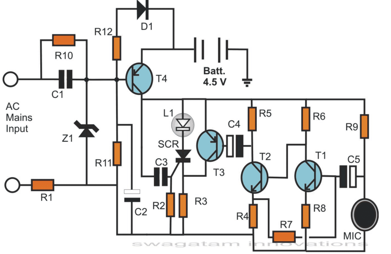
There are three primary sections to the circuit:
Transformerless Power Supply: This phase controls the electricity coming from the AC mains.
Capacitive Power Supply (C1, R10, R1, Z1): To safeguard delicate components, R1 restricts the initial surge current coming from the mains.
The AC current is delivered to the zener diode section by C1, which avoids it.
Only positive half-cycles are permitted by the zener diode (Z1), which controls the voltage from C1 up to a predetermined limit (12 volts in this example). To provide additional surge control, negative half-cycles are shorted to ground.
In order to give the circuit a smoother DC voltage, C2 filters the rectified DC output from the zener diode.
Transistor T4 is biased by resistor R10. On the other hand, T4's base receives a positive voltage from mains power, which blocks any negative voltage from getting to it. T4 is kept off by this.
When T4 is turned off, the LED remains off because the battery voltage that is linked to its emitter is prevented from entering the LED circuit.
The positive voltage at T4's base vanishes when mains power is cut off.
T4 can now be turned on because the ground potential from R11 can now reach its base.
The battery voltage can pass through T4's collector because of its conducting.
This voltage causes a brief current to flow through capacitor C3, activating the silicon controlled rectifier (SCR) and maintaining its latch even after C3 has charged.
The LED is turned on by the latched SCR, which permits current to flow to it. As long as there is no mains electricity, this condition continues.
T4 quickly switches off the battery to restore the circuit to its initial condition with the LED off when mains power is restored.
The "Puff" extinguishing feature is only active when the mains power is off.
This function enables "puffing" air on a microphone (MIC), like to blowing out a candle, to extinguish the LED.
On the MIC, a little electrical signal is produced by a puff of air.
This weakened signal is amplified by transistors T1, T2, and T3.
T3 disrupts the SCR's "latch" function by applying a positive voltage to the anode when it conducts. As a result, the SCR and LED are turned off.
When main power is on, Diode D1 permits a little current to gradually charge the battery.
This explanation covers the power supply of the circuit, the distinctive "puff" extinguishing characteristic, and switching dependent on the presence of the mains.
Construction
Using the provided schematic design as a reference, solder the electronic components onto a veroboard.
Place the LED atop a long, cylindrical plastic pipe to make it look like a genuine candle.
Keep the circuit board in a different, appropriate plastic box.
As indicated by the diagram, fasten the box and the pipe together.
There are two ways to power the device:
AC Mains: Attach two AC plug-in pins to the box so that it may be connected straight to a socket outlet.
Battery Power: To obtain the necessary 4.5 volts, house three 1.2 volt rechargeable penlight batteries within the pipe and link them in series.
Make sure the batteries you select can be recharged to save on replacements over time.
Parts List
R1, R3 = 47 Ohms, 1Watt = 2
R4 = 1 K = 1
R5 = 3K3 = 1
R2, R6 = 10 K = 2
R7 = 47 K = 1
R8, R12 = 150 Ohms = 2
R9 = 2K2 = 1
R10 = 1 M = 1
R11 = 4K7 = 1
C1 = 1 µF, 400V = 1
C2 = 100 µF/25 V = 1
D1 = 1N4007 = 1
C3 = 1 µF = 1
C4, C5 = 22 µF/ 25 V = 2
T3, T4 = BC557 = 2
T1, T2 = BC547 = 2
SCR = Any type, 100 V, 100 mA = 1
LED = White High Bright, 5 mm = 1
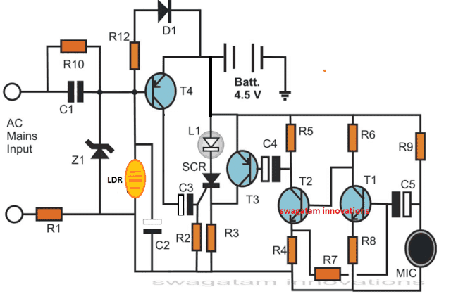
Turning on the electronic candle with an LDR:
It is possible to alter the current design such that it reacts to light, simulating lighting a candle with a match.
A light-dependent resistor (LDR) is used as a light sensor to do this.
The modification is shown in the diagram that is supplied. As you can see, the LDR has taken the role of resistor R11, which was previously used to bias the transistor.
The LDR shows extremely strong resistance in the dark. As a result, the SCR remains off and the LED cannot turn on.
The LDR's resistance decreases as a lighted match is brought close to it. As a result, the SCR is triggered and latches when current passes through the transistor.
The LED turns on and emulates a lighted candle while the SCR is latching, allowing current to flow to it.