
This article presents a strong DJ MOSFET amplifier circuit design that is rather simple to construct and can generate a powerful 250 watts of music into a 4 ohm loudspeaker.
The output's use of HEXFETs guarantees enormous current and voltage amplification.
This 250 watt MOSFET amplifier design offers great and effective voltage and current amplification due to the use of HEXFETs, or MOSFETs, in the output stage.
Impressive characteristics of the circuit include adjustable quiescent current, external offset voltage, and minimal distortion.
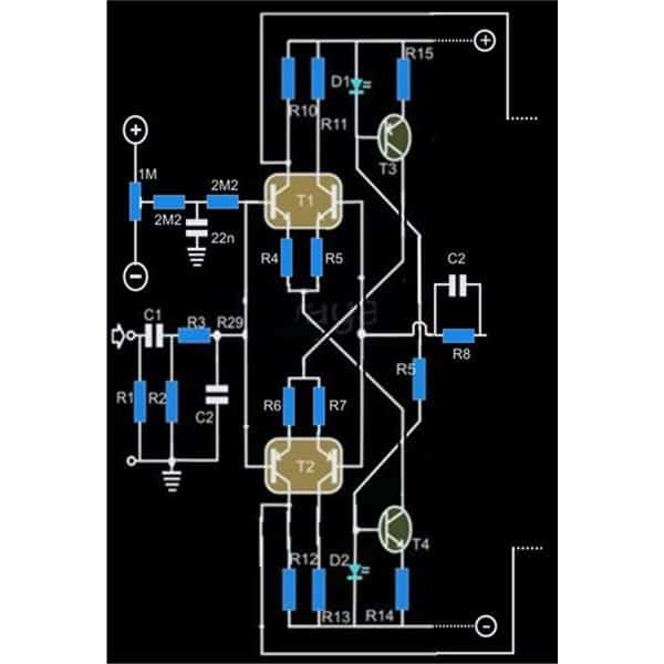
Amplifier Input Stage

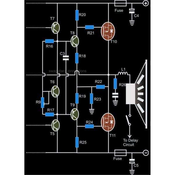
Amplifier Power Output Stage
Circuit Description
You may use this amazing 250 watt mosfet amplifier circuit as a DJ amplifier at events like concerts, parties, open spaces, etc.
Because the design is symmetrical, there are very few distortions. As we attempt to examine the circuit details:
The circuit schematic shows that two differential amplifiers make up the majority of the input stages.
Although the transistors in blocks T1 and T2 are identically matched dual transistors in a single package, you are free to choose separate transistors as long as their hFEs match exactly. For the NPN and PNP variations, make use of a few BC 547 and BC 557, correspondingly.
The best technique to integrate two signals is probably using a differential setup, as seen above, where the input and feedback signals are effectively blended.
The amplification of this stage is typically determined by the ratio of T1's collector/emitter resistances.
Two transistors, T3 and T4, provide the DC operational reference for T1 and T2, as well as the corresponding LEDs.
The aforementioned LED/transistor network also aids in giving the input stage a steady current source because it essentially isn't affected by changes in the surrounding temperature. However, the LED/transistor pair should ideally be joined by soldering them very close to one another across the PCB or by glue.
The network made up of R2, R3, and C2 provides an efficient low pass filter and aids in keeping the bandwidth at a level appropriate for the amplifier just after the coupling capacitor C1.
A further little network at the input, consisting of a 1M preset and a few 2M2 resistors, aids in regulating the off-set voltage to maintain the amplifier's DC component at zero potential.
The introduction of an intermediate driver stage, consisting of T5 and T7, follows the differential stage.
The T6, R9, and R17 combination works as a sort of variable voltage regulator to control the circuit's quiescent current usage.
The output power stage, which includes the HEXFETs T10 and T11, receives the boosted signal from the previous stage and sends it to the driver stage, which is made up of T8 and T9. From there, the signals are amplified greatly in terms of both current and voltage.
It is evident from the figure that T10 is a p-channel and T11 is an n-channel FET.
At this point, the setup enables effective voltage and current amplification.
However, the total amplification is restricted to 3 because of the R8/C2 and R22/R23 feedback circuitry. The restriction guarantees little distortion at the output.
Here, the output stage utilizing HEXFETs has a clear benefit over its more traditional counterpart, in contrast to bipolar transistors.
Positive temperature coefficient devices, such as HEXFETs, have an innate ability to restrict their drain source as the case temperature rises. This feature protects the device from thermal runaway conditions and burnout.
As the loudspeaker's impedance rises at higher frequencies, resistor R26 and the series capacitor balance it out.
Positioned to protect the speakers from rapidly increasing peak signals is inductor L1.
Parts List
| Component | Value | Additional Info |
|---|---|---|
| R1 | 100KΩ | = 1 (quantity) |
| R2 | 100KΩ | = 1 (quantity) |
| R3 | 2KΩ | = 1 (quantity) |
| R4, R5, R6, R7 | 33Ω | = 4 (quantity) |
| R8 | 3.3KΩ | = 1 (quantity) |
| R9 | 1KΩ | PRESET = 1 (adjustable) |
| R10, R11, R12, R13 | 1.2KΩ | = 4 (quantity) |
| R14, R15 | 470Ω | = 2 (quantity) |
| R16 | 3.3KΩ | = 1 (quantity) |
| R17 | 470Ω | = 1 (quantity) |
| R18, R19, R21, R24 | 12Ω | = 4 (quantity) |
| R22 | 220Ω | 5 WATT = 1 (power rating) |
| R20, R25 | 220Ω | = 2 (quantity) |
| R23 | 56Ω | 5 WATTS = 1 (quantity and power rating) |
| R26 | 5MΩ | ½ WATT = 1 (resistance and power rating) |
| C1 | 2.2uF | PPC = 1 (unclear what PPC refers to) |
| C2 | 1nF | = 1 (quantity) |
| C3 | 330pF | = 1 (quantity) |
| C6 | 0.1uF | mkt = 1 (material type) |
| T3 | BC557B | = 1 (quantity) |
| T4 | BC547B | = 1 (quantity) |
| T7, T9 | TIP32 | = 2 (quantity) |
| T5, T6, T8 | TIP31 | = 3 (quantity) |
| T10 | IRF9540 | = 1 (transistor type) |
| T11 | IRF540 | = 1 (transistor type) |
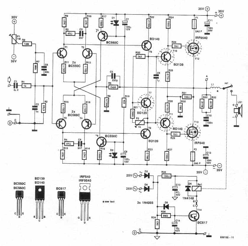
The accompanying figure, which includes all the component specifications, shows an alternative version of the previously described 250 watt power amplifier: