Have you ever seen remarkable LED modules with high power and high efficiency and considered utilizing them in construction? This tutorial takes you step-by-step through building a 100-watt LED floodlight with one of these modules.
An explanation of the fundamental electrical circuit (driver circuit) needed to run a powerful LED module safely for its intended use in lighting is given in this article along with an update to the technical specifications (datasheet).
As opposed to the earlier discussions of smaller LEDs, this article centers on a high-power LED module. It investigates possible home lighting applications for this 100-watt LED module, possibly at a five-times cheaper cost than conventional lighting solutions.
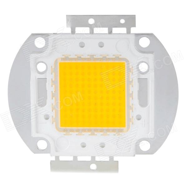
Image of a 100 Watt LED Module

LED Lighting: A Strong and Effective Source of Light
LEDs are well known for their outstanding energy efficiency. LED technology makes it possible to create high-intensity lighting installations with much less power consumption than traditional lighting. Reduced heat emissions from this lower power consumption also help the environment by reducing the effect of global warming.
The Development of LEDs with High Power
Innovations in technology keep releasing LEDs' full potential, with amazing outcomes. The 100-watt LED module is one such innovation. It only takes up 100 watts of power and produces an amazing 6500 lumens of light output, all while being small (about 40 square millimeters).
Performance and Energy Savings
When compared to other light sources, these modules are estimated to provide five times the energy savings. In comparison, a traditional halogen lamp that may use more than 500 watts would produce light output of 6500 lumens.
A Layman's Guide to Understanding Key Features
Let us examine the main features of this remarkable LED module, providing an easy-to-understand explanation for individuals lacking technical expertise.
100 Watt LED General Specifications
- Color: White (suitable for most lighting applications)
- Power Consumption: 100 watts
- Color Temperature: Up to 6000 Kelvin (white color)
- Light Output: 6500 lumens
- Operating Voltage: Around 35 volts
- Operating Current: Around 3 amps
- ESD Level: Up to 4000 volts
- Operating Temperature Range: -40°C to 110°C
- Viewing Angle: Up to 120 degrees
- Dimensions: 4.3 mm (height) x 56 mm (length) x 40 mm (width)
Maximum Ratings
- Type: 100W COB LED
- Color Rendering Index (CRI): Ra70-80 / Ra80-85 / Ra90-95 / Ra95-98 (depending on selection)
- Forward Current (IF): 3500mA
- Forward Voltage (VF): 29-34 volts
- Chip Category: Bridgelux
- Power Output: 100 watts
- Beam Angle: 120 degrees
- Illumination Magnitude: 10000-14000 lumens
- Substrate: High-grade copper
- Color Correlated Temperature (CCT): 3000K, 4000K, 5000K, 6000K (customizable)
- Applications: Spotlights, moving head lights, stage lighting, photography, high-intensity floodlights, etc.
Acceptability in a 20-Square-Meter Space:
According to the specifications, a 20 square meter area can be sufficiently lit by this 100W COB LED. The high lumen output (10000–14000 lumens) is within the usual flood light output range. The precise amount of light achieved in a given area, however, will vary depending on a number of variables, including the height of the ceiling, the type of lighting needed (general vs. task), and whether the space has any reflective surfaces.
Important characteristics of the 100-Watt LED Module:
High Lumen Maintenance: Continues to produce light even after prolonged use.
Robust mechanical specifications ensure minimal wear and tear and resistance to environmental variations in the durable construction.
Dependable Performance: Preserves peak performance over the course of its life.
After going over the main characteristics of the module, it's a good idea to investigate a suggested circuit that can safely and within its operating parameters drive this 100-watt LED.
Constructing a 100-Watt LED Floodlight Driver with Current Control
This section describes a straightforward two-transistor LED driver circuit that can effectively limit current. The 100-watt LED module that was previously discussed can be transformed into a potent floodlight using this circuit.
Presently, the design provides a flexible and uncomplicated method of current limiting, especially when cost-effectiveness is a primary consideration. Although low-current applications may have been the focus of earlier discussions, this circuit is specifically designed to handle high currents, making it suitable for driving LEDs with a wattage of up to 100.
Circuit Diagram

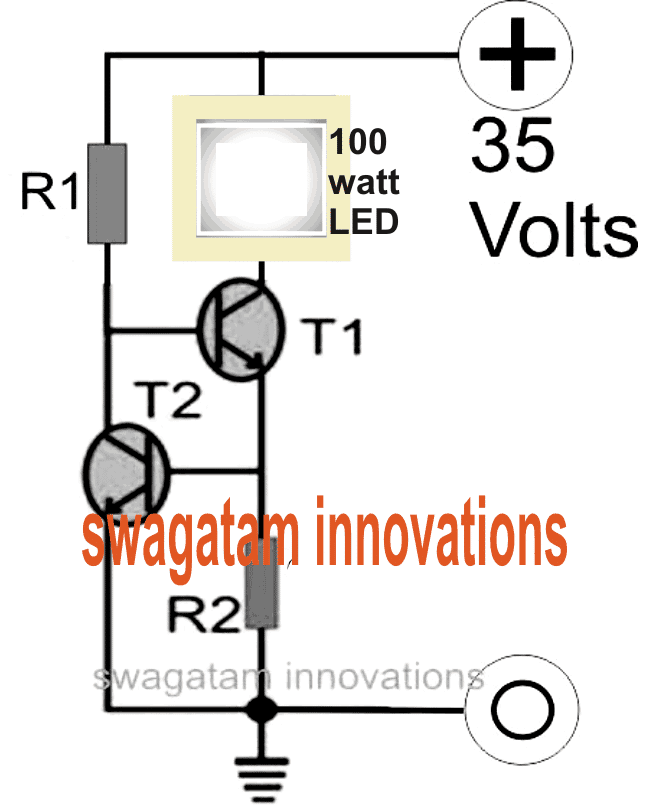
Circuit Breakdown
Two transistors (T1 and T2) are used in the circuit in a coupled configuration. The base of the upper transistor (T1) is loaded by the collector of the lower transistor (T2). T1 does not directly control the main LED current, even though it manages it. Rather, the current is managed by adjusting T1's base current.
Current Sensing and Regulation:
T1's emitter is connected to a current-sensing resistor. The LED current is transformed into a voltage drop by this resistor. Transistor T2 stays off as long as this voltage drop stays below 0.6 volts, which is the minimum base-emitter voltage required to activate T2. T2 activates, though, if the LED current rises to the point where the voltage drop across the resistor is greater than 0.6 volts.
Current Limiting and Feedback Loop:
T2 effectively clamps T1's base voltage when it turns on, decreasing T1's conductivity. By temporarily cutting off the LED's current, this action resets the voltage drop across the current-sensing resistor to zero.
A feedback loop is created by quickly (many times per second) turning on and off the LED, keeping the current within safe, predetermined bounds.
Choosing the Maximum Current:
Resistor R2's value is crucial. It is designed to make sure that, until the LED current reaches the target value (in this case, 100 watts), the voltage drop across it stays below 0.6 volts. The feedback loop kicks in to regulate the current back to the safe operating range once it surpasses this limit.
Safety Notice:
Recall that effective heat dissipation is essential. Make sure the heatsink on which the LED is mounted is the right size according to the LED datasheet's specifications.
Calculating Resistor Values in a Current-Controlled LED Driver:
The passage describes how to determine the resistor values (R1 and R2) in a circuit that uses two transistors to regulate current for a high-power LED.
- R1: Base Resistor for T1
- The formula calculates the resistance needed for the base resistor (R1) of the upper transistor (T1).
- Variables:
- Us: Supply voltage (not provided in the excerpt).
- Hfe: Current gain of transistor T1 (assumed to be 30 in this example).
- Load Current: Current flowing through the LED (calculated as 100 watts / 35 volts = 2.5 amps).
- By adjusting R1, we can control the base current of T1, which in turn controls the collector current (current flowing through the LED).
- R2: Current Sensing Resistor
- This resistor creates a voltage drop proportional to the current flowing through the LED.
- The formula calculates the value of R2 needed to generate a voltage drop sufficient to activate the lower transistor (T2) when the LED current reaches the desired limit.
- Here, the formula uses the LED current (2.5 amps) and a threshold voltage of 0.7 volts (likely the base-emitter voltage of T2).
- Wattage Ratings
- The passage also calculates the power dissipation (wattage) required for each resistor based on the chosen values and circuit voltage.
- It's crucial to select resistors with wattage ratings exceeding the calculated values to ensure safe operation.
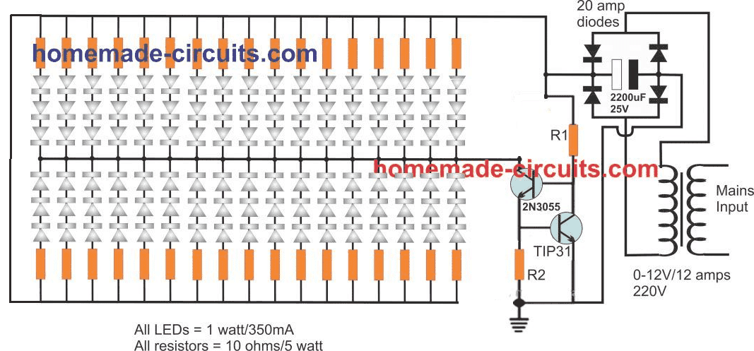
Complete Schematic for a 100-watt LED Light with Current Control