
This tutorial will teach you how to build amazing LED circuits with flashing, fading, and blinking lights using the IC 555 chip. We'll tweak and enhance the fundamental design a little bit.
Why This is a Great Use for the IC 555:
The "astable mode" setting on the IC 555 allows it to function as a continuous oscillator. This oscillator may be used to regulate the blinking of LED lights when it operates slowly enough.
We can use the LEDs to generate a variety of patterns and effects by adjusting the wires that are linked to the chip's output.
What We're Going to Construct:
This article will walk you through a few methods for doing this and include circuit schematics for items such as:
- Basic LED flashers
- A generator of the "ghost effect"
- Changing blinkers
- Dimmers for lights
The IC 555 - A Companion for Hobbyists:
This tutorial uses the popular IC 555 chip to create a few simple and entertaining LED flasher circuits.
The fundamental flashing feature will remain intact, but the circuit will be modified in various ways to adjust the rate and pattern of the LEDs' blinking.
A flexible chip that amateurs may utilize to create a variety of intriguing circuits is the IC 555. It may be configured to function in a variety of ways.
Although the IC 555 has various applications, flashers are one of its most well-liked uses.
Depending on your preferences, these circuits may be used to blink any kind of light, including LEDs, flashlights, string lights, and standard house lights.
Constructing the Flasher:
We put the IC 555 to the basic astable mode so that it will function as a flasher. To get this running, just a few resistors and capacitors are needed.
Once the chip is configured in this mode, there are several methods to modify the output to produce captivating visual effects.
Let's start by learning how to use the IC 555 to construct a few awesome LED circuits. However, we must first gather our supplies.
What You'll require:
You most likely already have a variety of resistors and capacitors in your collection as a hobbyist. You just need a limited assortment of resistors and capacitors in various values for these tasks.
Bill of Materials
- Resistors rated at ¼ watt, 5 %, unless otherwise stated.
- Resistors – 1 K, 10 K, 680 Ω, 4.7 K, 100 Ω, 820 Ω, 1 M etc. = 1 each
- Capacitors – 0.01 µF, 470 µF, 220 µF, 1 µF = 1 each
- Zener diode – 5.1 volts, 400 mW = 1
- LEDs – Red, Green, Yellow 5mm
- IC 555 = 1
IC 555 Pinouts


IC 555 Circuit for Producing Flashing and Fading LED Effects


The fundamental setup for a 555 IC LED circuit is depicted in the first image. It is linked as an astable multivibrator in this instance.
You may play with the resistors and the 1 uF capacitor to produce various blinking rates over the attached LED.
Other colors can also be utilized with the LEDs.
To increase the LED's intensity, a resistor of lower value can be used in place of the 1 K resistor; nevertheless, the resistor's value shouldn't be lowered below 330 Ohms.
To give the circuit a changeable blinking rate feature, a possible solution is to use a pot instead of a 1 M resistor.
Creating an Effect of Police Revolving Lights
With the right modifications, the above-constructed circuit can have the appearance of a rotating, flashing police light.
As seen in the image, we may get a highly unusual effect with the LED illuminations by connecting a series of zener diodes, resistors, and capacitors to the circuit's output.
The LED produces the described police warning roof light signal illusion by glowing brightly at first, progressively dimming, and then sporadically pulsating at a high intensity.


Circuit for a Random Light Effect Generation
The circuit may be used to create random light patterns across the linked set of LEDs using the 555 LED arrangement seen in this diagram.
As can be seen, a few resistors, a capacitor, and three LEDs are linked.
The third LED varies at a different random rate, while the two parallel but oppositely polarized LEDs flash alternately at a specific beat.


The circuit below can be used to simplify the effect mentioned above.
In this case, the LED linked to the 1 K resistor blinks at a certain pace, while the LED behind it that is connected to the ground quickly flips at a different predetermined rate.


Giving the LED a Haunting Appearance
It is quite easy to create an odd lighting pattern over the LED by using a few resistors at the IC's output. This may be done with any of the previous circuits.
The illustration illustrates how the IC's output is specially linked to two resistors and one resistor.
The LED is abruptly turned ON by the network and gradually turned OFF, creating a very unsettling visual effect.


Alternately Flashing LED Circuit
As everyone knows, the circuit layout for an IC 555 LED is rather simple. Two LEDs may be connected to the IC output in order to create an alternative blinking pattern over the linked LEDs.


By completely rearranging the network using the indicated kind, the aforesaid circuit may be further customized as seen below.
Despite their alternating blinking, the LEDs in this instance may vary in brightness from dim to brilliant.


LED Fader with Adjustable Brightness using IC 555
The IC 555 circuit may be configured as per the below schematic to provide a very intriguing light fading effect.
When turning on or off the LED, the circuit does it extremely gently. Rather than turning it off suddenly, it does so very gradually.

Making a IC 555 Strobe Light
A pair of widely available integrated circuits, IC1, a 555 oscillator/timer, and IC2, an LM7812 fixed 12 volt regulator, serve as the foundation for the strobed LED lighting system schematic design shown in the following 555 LED circuit.
The ideal frequency and duty cycle for the oscillator (IC2) must be determined.


Stated differently, we are striving for the ideal balance between duty cycle and frequency.
Three hertz (Hz) and a fifty percent duty cycle are the operating frequencies for the circuit. With the use of a convenient 1 uF capacitor C2 connected between pin6/2 and ground of the 555 timer/oscillator, the operating frequency of this 555 strobe light circuit was found.
Q1's base, an NPN Darlington transistor TIP120, is connected to the 555 output (pin 3). Similar to a switch, the transistor responds to the oscillator output (555 IC2) by switching current, which causes the LED lighting module to flash.
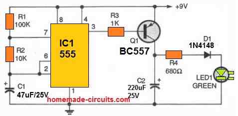
A circuit for a Firebird Light Flash Simulator, 555
Using a flashlight to draw fireflies isn't necessarily the most sophisticated approach to keep the youngsters entertained on summer evenings.

With respect to color, attack and decay durations, brightness, and frequency, this simple circuit simulates a firefly flash more faithfully, which makes it useful.
With the help of a 9-volt battery, our 555 LED firefly circuit can be programmed to replicate the flashing characteristics of any of the 125 different species of fireflies that are common in the nation. It also seems to last forever and doesn't require wet soil or bugs to feed.
Timing of a 555 timer, which generates an increased duty cycle square wave at 0.25 Hz, is controlled by R1, R2, and C1.
Flipping the output by means of the PNP transistor results in the smallest duty-cycle signal. The 220 uF capacitor discharges through the 680 ohm resistor (R4) and capacitor (C2), gradually reducing the green illumination of the green LEDs.
The result is an electric firefly which glows four times per second. The green flash may linger for approximately 30 seconds and exhibits unique attack and decay attributes.