
The Earth leakage circuit breaker designs that have been presented will keep an eye on the earthing line leakage current level of your home's electrical outlets and cut-off the electrical devices immediately as a problem is identified. In this article we'll discover two methods: the first uses simply transistors, and the second makes use of the IC LM324.
Caution: These ELCB circuits have not been tested in practice, thus thorough testing is essential before practical application. Each circuit utilizes mains AC, which can be hazardous if exposed and switched ON.
Overview
They are designed to immediately cut off the main electrical system and prevent any more losses in the event of a malfunction. We describe here a basic ELCB circuit.
This article describes the basic circuit of an Earth leakage circuit breaker, commonly known as a ground fault circuit interrupter.
After the circuit is constructed and put in place, it's going to quietly keep an eye on the "health" of your home's earth connection as well as the linked device.
As soon as it detects a broken earth connection or a current leak by means of the equipment's body, the circuit will instantly turn off the mains.
The Main Purpose of an ELCB
A short circuit in a home wiring is most likely less damaging compared to a current leak through an earth connector.
A short circuit vulnerability is evident and is often addressed with a circuit breaker or fuse.
Earth current leaks, however, can go unnoticed for years, depleting your energy supply and damaging or destroying equipment and wiring.
Furthermore, the leakage might become a fatal shock throughout the equipment's body if the earth cable has not been grounded correctly because of defective conduction or fracture.
ELCB using Transistors
Circuit Description
Instead of sensing incoming or leaking voltage, the suggested ground fault circuit interrupter, or ELCB, uses the straightforward method of monitoring the AC signal.
In this case, a basic audio amplifier stage is used to efficiently sense the electrical leakage as a frequency since the leaking AC might be too little to be identified as a possible variation using a basic voltage detection circuit.
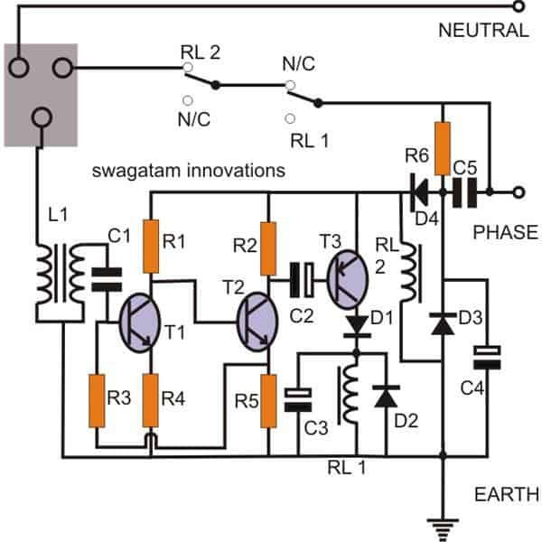
The primary detection step of the device is a straightforward bootstrapped amplifier network, as seen in the diagram. The passive parts that go with transistors T1 and T2 are connected to create a tiny two-stage amplifier.
When R3 is added, the circuit evolves into more robust and responsive to even the smallest input signals since it gives a positive feed back to the input.
Basically, the inductor L1 incorporates a pair windings: the main winding, that is linked to the socket's earth point, includes fewer turns than the secondary winding, which includes an additional six turns and is coupled to the circuit's input through C1.
L1's function is to increase any AC generated into its primary winding, that only becomes possible if there is a leak via the body of an equipment that is plugged into the outlet.
The enhanced leakage voltage mentioned above is amplified more dramatically to the point where it triggers RL1, immediately cutting off the gadget's input and displaying the earth leakage problem.
The circuit is powered by a typical transformerless power supply, which is formed by capacitors C5, D3, and C4.
Rectifying and suppressing spikes are the two tasks that D3 does. It's important to note that the primary earth connection on its own switches from being the neutral line to the circuit's negative.
Also, because RL2 has a direct link to the supply throughout the positive of the circuit and the earthing, in the event the earthing weakens or disconnects, the relay might disengage, removing off the AC mains to the appliance itself, indicating the overall condition of the earthing and protecting the house from malfunctioning or missing earth connections.
ELCB Circuit Parts List.
| Component | Specifications | Quantity |
|---|---|---|
| Resistors | ||
| R1 | 22K | 1 |
| R2 | 4K7 | 1 |
| R3 | 100K | 1 |
| R4 | 220Ω | 1 |
| R5 | 1K | 1 |
| R6 | 1M | 1 |
| Capacitors | ||
| C1 | 0.22uF / 50V | 1 |
| C2 | 47uF / 25V | 1 |
| C4 | 10uF / 250V | 1 |
| C5 | 2uF / 400V PPC | 1 |
| Transistors | ||
| T1, T2 | BC 547B | 2 |
| T3 | BC 557B | 1 |
| Relays | 12V, 400 Ohm, SPDT | (Varies) |
| Diodes | 1N4007 | (Varies) |
L1 = Coil coiled around a bobbin (smallest size) typically used with E-cores; start winding 50 turns of 25 SWG wire first, then hook it up and solder it to create the primary terminals at the bobbin's side.
Proceed to wind 300 turns of the primary winding employing 32 SWG copper wire. Once again, attach both ends to the opposite side of the bobbin with solder. Place the coil within the E-cores and secure it. Wrap it down firmly with PVC.
Earth Leakage Breaker (ELCB) Unit Using IC 324
An emergency electrical device called an earth leakage circuit breaker is used to detect current leaks via the "earthing" terminal and turns off the electrical supply whenever the leakage reaches a specific unsafe threshold.
Introduction
These devices are often created implementing electromagnetic techniques; fortunately, in this article, we'll look at how to make an ELCB using common electrical components and why an electronic equivalent is superior compared with an industrial electromagnetic one.
An electrical ELCB may be built in three different ways: the first utilizes a relay to do the switching; the second idea incorporates a triac; and the third concept uses the solid-state relay, or SSR, to do the necessary operations.
The triggering mechanism for each of the aforementioned concepts uses an input inductor stage.

Circuit Working
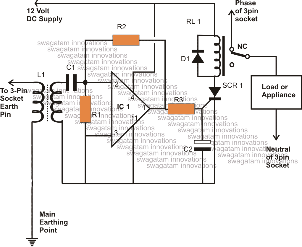
The design is centered around a single Opamp from the IC 324, which can be seen in the image. The op amp is set up to operate as an inverting amplifier with high gain.
By changing the value of R2, which increases the sensing capability of the circuit, the op amp's sensitivity may be modified. It is designed as a high gain AC amplifier.
The coupling capacitor C1 selects any momentary AC signal that could be existing at the IC's inverting input #2, amplifying it immediately.
The IC's upper input is linked to a tiny inductor transformer.
The inductor's primary has a connection to the wire that, in the end, finishes at either the earthing termination or a pin on one of the many three-pin outlets throughout the building.
The transformer utilized in the output amplifier stage of a tiny radio receiver might be a standard output transformer.
In the event of a leakage, the flowing current travels across the inductor's primary winding before increasing in strength at the secondary winding.
The IC input instantly detects the amplified induced AC and intensifies it higher to the required levels, causing the SCR to flip in accordance with the triggering.
Because of its innate feature, the SCR latches instantaneously and draws the relay into activation.
In order to turn off the gadgets and remove earth leakage problems, the relay switches ON and turns off the main electrical supply to the three-pin outlets.