
In this article, we'll talk about a straightforward machine gun sound effect generator circuit that just requires a few resistors and three 74LS04. An IC that functions as a hex NOT gate is the IC 74LS04.
It comes in a single box with six NOT gates or inverters. Every gate comprises an input and an output endpoint.
The logic that is produced at the gates' output, as the name implies, is going to be precisely the opposite of that which is given at the input level.
Analyzing the ICs' configuration as a superb AK-47-like sound effect generator can help us better grasp how they are set up.

How the Circuit Works
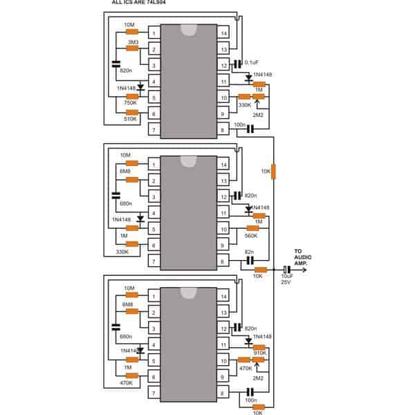
As can be seen in the enclosed circuit schematic, the unit basically consists of three almost identical IC configurations.
The pulses produced at the output of each section have their own distinct push pull ratios. These are integrated together and superimposed simulating exact machine gun shots.
Looking carefully, the circuit reveals that the six inverters from each of the IC are wired up as three astable multivibrators connected in series to each other.
The outcome quite replicates sound coming from three discrete firing posts, situated at some distance away.
Because each astable's series connections are made using diodes, the latter can only oscillate when the former is either not functioning at all or has zero logic.
It is evident that two components of the circuit have potentiometers, while the final section is control-free. The frequencies of the pertinent AMVs, which influence the frequency of gunfire noises, are adjusted via potentiometers.
The 74LS series' participation guarantees the lowest possible current consumption, and this is often limited to 2 mA at 5 volts.
Unfortunately, because of their low loudness, the produced pulses cannot directly power loudspeakers.
To experience the realistic FEEL of the thundering gun fire simulations, the terminated output can be appropriately merged with an audio amplifier.
The most effective machine gun sound effect can possibly be replicated and optimized by adjusting the pots outside.
It is possible to construct the whole machine gun sound effect circuit on a generic PCB and install it within the audio amplifier housing. The amplifier's power supply can be used to power the circuit.
Schematic Design

Parts List
| Component | Specifications | Quantity |
|---|---|---|
| Resistors | 1/4 watt 5% | |
| 10 MΩ | 3 | |
| 5.6 MΩ, 4.7 MΩ, 3.9 MΩ, 120 kΩ, 39 kΩ, 470 kΩ, 680 kΩ | 1 each | |
| 820 kΩ | 3 | |
| 560 kΩ | 2 | |
| 390 kΩ | 2 | |
| 1 MΩ | 3 | |
| Preset 1 MΩ | 2 | |
| Preset 4.7 kΩ | 1 | |
| Capacitors | ||
| PPC | 820 nF | 6 |
| 82 nF | 3 | |
| Electrolytic | 1 µF, 16 V | 2 |
| Diodes | 1N4148 | 6 |
| IC | 4049 | 3 |
Interesting Feedback from an avid reader
After some analysis, I've come to the conclusion that the 4049 concept is lot easier as opposed to I initially thought.
The final two inverters in each chip are the only parts that really generate fire. I have one chip that I can use to activate the machine gun.
It will seem authentic if you use two sets of two inverters each, produce two identical output noises, and delay one by a few microseconds. As it is now constructed, I would prefer not to hear three distinct machine gun noises. The 4069 chips, which share the same pin arrangement as the 74LS04, are still in use.
View the explanation that follows:
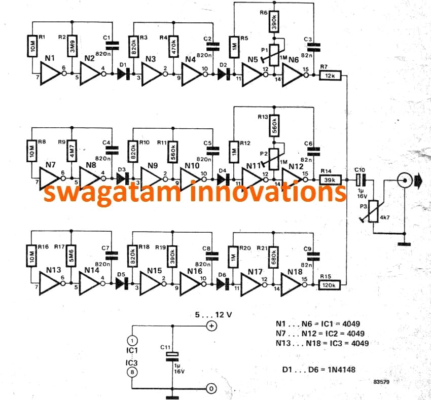
Performance of CD 4049 machine gun sound: According to the diagram, the first oscillator section of CD 4049 IC #1 is provided by the N1 and N2 gates.
Timing of the output is caused by R1, R2, and C1 variables. After around three seconds of high output, pin 4 has a four-second period of low output. The subsequent oscillators (N3 & N4) start oscillating as the output drops.
Pin 4 on N2 is low for four times while pin 10 on N4 is low. N5, N6, R5, R6, P1, and C3 create the real firing of machine guns, which is set off each time N2's pin 10 drops low. To imitate fire, N6 pin 15 gives a pulsed output. P1 modifies the output (fire) pulse rate.
Longer time periods between gun firing bursts are made possible by slight resistance adjustments to the second chip, which otherwise operates on the same principle.
The third chip operates similarly, with output bursts that differ from those of Chips 1 and 2. On Chip 3 pin 15, the output pulse rate remains constant and cannot be changed.
The resistors at pin 15 on the three chip outputs are of varying sizes: 12K, 39K, and 120K. The output of pin 15 will vary in pulse intensity.
It produces the sound effects of three machine guns fire consecutively from close and far away as soon as it is switched on and hooked to an amplifier.