
Would you like to build a precise electronic thermostat for your fridge? The "cool" features of the three distinct solid state thermostat designs covered in this article will take you by surprise.
What is a Thermostat
As everyone knows, a thermostat is a device that can sense a specific fixed temperature level and trip or switch an external load. These devices might be either more complex electrical or electromechanical in nature.
Appliances that cool, refrigerate, and heat water are commonly linked to thermostats. In these kinds of applications, the gadget becomes an essential component of the system; otherwise, it can reach high temperatures, begin to function in them, and eventually sustain damage.
The aforementioned appliances include control switches that may be adjusted to guarantee that the thermostat turns off the power to the appliance when the temperature reaches the desired limit and turns back on when the temperature drops below the threshold.
As a result, comfortable temperature ranges are maintained within refrigerators or at room temperature with the use of air conditioners.
This refrigerator thermostat circuit may be applied externally to regulate the temperature of a refrigerator or any other appliance of a same kind.
The thermostat's sensing element can be attached to the exterior heat-dissipating grid, which is typically located behind the majority of Freon-using cooling units, to regulate their functioning.
In comparison to built-in thermostats, the design is more adaptable, versatile, and capable of higher levels of efficiency.
The circuit is significantly less expensive than traditional low-tech circuits and can simply replace them.
Now let's see how the circuit operates:
Circuit Working

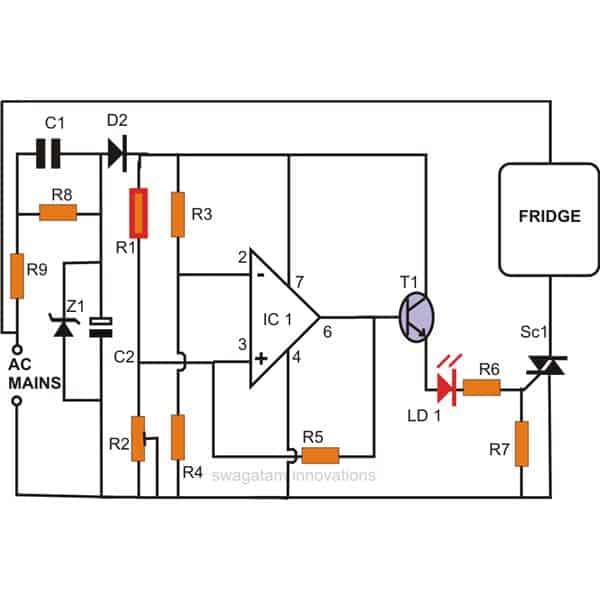
A straightforward circuit centered on the IC 741, which is essentially set up as a voltage comparator, is depicted in the schematic next to it.
Here, a transformerless power supply is used to create a tiny, solid-state circuit.
The primary sensing components of the circuit are formed by a bridge arrangement with R3, R2, P1, and the NTC R1 at the input.
Using a voltage divider network consisting of R3 and R4, the IC's inverting input is clamped at half the supply voltage.
As a consequence, the IC no longer needs a dual supply, and the circuit may still operate at peak efficiency with a single pole voltage supply.
With regard to the NTC (Negative Temperature Coefficient), the setting P1 fixes the reference voltage to the IC's non-inverting input.
The NTC resistance decreases and the potential at the IC's non-inverting input passes the specified reference if the temperature under check begins to stray over the intended values.
This immediately flips the IC's output, which flips the output stage made up of a transistor and triac network, cutting off the load (the cooling system or the heating system) until the temperature drops below the lower threshold.
In certain ways, the feedback resistor R5 aids in introducing hysteresis into the circuit. This is a crucial component since without it, the circuit may continue to flip-flop quickly in response to abrupt temperature fluctuations.
After assembly is finished, the circuit may be easily configured using the following points:
A LOT OF CAUTION IS ADVISED DURING THE TESTING AND SETTING PROCEDURE DUE TO THE FACT THAT THE WHOLE CIRCUIT IS AT AC MAINS POTENTIAL. ALSO USE ELECTRICAL TOOLS WHICH ARE THOROUGHLY INSULATED NEAR AND AROUND THE GRIPPING AREA. IT IS STRICTLY RECOMMENDED TO USE A WOODEN PLANK OR ANY OTHER INSULATING MATERIAL UNDER YOUR FEET.
Setting Up the Circuit for This Electronic Refrigerator Thermostat
To precisely set the thermostat circuit's cut-off threshold level, you'll need a sample heat source.
Turn on the circuit, add the heat source mentioned above, and secure it with the NTC.
Now tweak the setting such that the output simply toggles (the output LED illuminates).
Depending on the circuit's hysteresis, remove the heat source from the NTC; the output should turn off in a few seconds.
To ensure that the process is operating correctly, repeat the steps many times.
The refrigerator thermostat has now been configured to perfection and is prepared to be incorporated with any refrigerator or similar device for precise and long-lasting operation regulation.
Parts List
Resistors:
- R1: 10kΩ NTC thermistor (resistance changes with temperature)
- R2: 10kΩ preset resistor (adjustable)
- R3 & R4: 10kΩ resistors
- R5: 100kΩ resistor
- R6: 510Ω resistor
- R7: 1kΩ resistor
- R8: 1MΩ resistor
- R9: 56Ω 1W resistor
Capacitors:
- C1: 105nF 400V capacitor
- C2: 100uF 25V capacitor
Diodes:
- D2: 1N4007 diode
Zener Diode:
- Z1: 12V 1W zener diode
Fridge Thermostat using IC LM324
Below is an explanation of another straightforward yet efficient electronic fridge thermostat circuit. The request that Mr. John provided me served as the basis for this piece.
The major active component of the suggested concept is a single IC LM 324. Let's investigate further.
The electronic mail I got from Mr. John
Circuit Objective
John here, from UK. You seem to have knowledge of thermostats and other electronic designs, so perhaps you might assist me. The mechanical fridge thermostat has to be replaced since it is broken. I apologize for not writing on the blog directly. I believe there is too much text.
I made the decision to construct a new schematic.
It functions effectively, but only in warm weather. To utilize VR1 to set the temperature inside the refrigerator in the range of -5 Celsius + 4 Celsius, like the previous thermostat knob used to do, I need the schematic to function between -5 Celsius and +4 Celsius.
LM35DZ is used in the schematic (0 Celsius to 100 Celsius). LM35CZ (-55 to +150 degrees Celsius) is what I'm using. I connected an 18k resistor between pin 2 of the LM35 and pin 4 of the LM358 to force the LM35CZ to send negative voltage. (as in the datasheet's page 1 or picture 7).
[Lim35.pdf] at https://www.ti.com/lit/ds/symlink.
Using a 5,2 volt stable power source, I made the following adjustments:1. ZD1 and R6 are no longer available. 550 ohms is R5.
Since I couldn't locate a 2,2K pot, VR1 is 5K instead of 2,2K. The design is inoperable at temperatures below 0 Celsius. What further changes should I make?I measured a few things.
At 24°C, the LM35CZ provides 244mVA; at -2°C, it provides -112mV, and at -3°C, it provides -113mV.The voltage between TP1 and GND may be adjusted from VR1 between 0 and 2,07 volts at -2 Celsius. I'm grateful.
Evaluation of the Circuit:
The answer is most likely far more straightforward than it might seem.
Because it only has one source, the circuit essentially responds to positive temperatures alone.
Dual supply voltages must be delivered into the circuit, or more specifically, the op amps, in order for it to react to negative temperatures.
That should take care of the problem without requiring any changes to be made to the circuit.
LM35 and TL431 integrated circuits can be quite unknown and challenging to configure for novice hobbyists, even though the circuit above appears excellent.
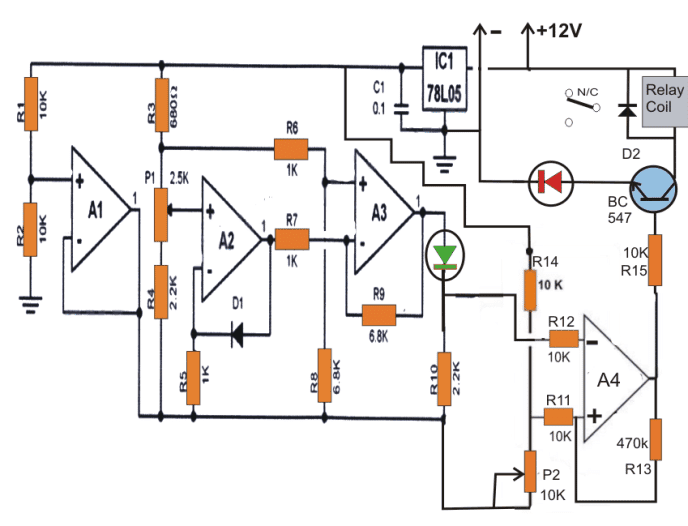
A single integrated circuit (IC) LM324 and a common 1N4148 diode used as the sensor can be used to create a circuit akin to an electronic refrigerator thermostat.
The straightforward wiring around a quad opamp IC LM324 is seen in the diagram below.
To the sensing circuit operation, A1 generates a virtual ground.
amps, so eliminating convoluted and large wiring and easily creating a dual voltage supply.
The sensor stage, which is formed by A2, uses the 1N4148 "garden diode" to sense temperature throughout.
The differences produced by the diode are amplified by A2 and sent to the following step, where A3 is set up as a comparator.
Finally, the output of A4 is used to provide the final result to the next relay driver stage and another comparator stage that also includes A4.
The preset P1 settings are used by the relay to regulate the fridge compressor's On/OFF switching.
As per the user's request, P1 should be configured such that the green LED simply turns off at -5 degrees or any other lower temperature.
P2 should then be changed such that the relay only activates in the scenario mentioned above.
A 1M preset should really take the place of R13.
Depending on the user's preferences, this setting should be changed so that the relay simply deactivates at about 4 degrees Celsius or any other closer numbers once more.

Cold Sensor Fridge Thermostat
Mr. Sukovo, one of my ardent blog followers, asked me to explain the third circuit concept.
I had previously published a circuit for an automated refrigerator thermostat that was similar, but it was designed to detect greater temperatures that were available at the refrigerators' back side grid.
Mr. Sukovo did not completely get the notion and requested me to create a refrigerator thermostat circuit that sensed the cold temperatures within the refrigerator instead of the hot ones at the back.
I was able to find the current refrigerator temperature controller's circuit diagram with a little bit of work, so let's review the concept using the following points:
How the Circuit Functions
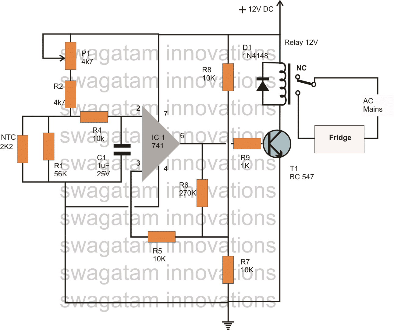
This application of the standard comparator notion is not particularly novel or inventive.
Both the conventional comparator mode and the non-inverting amplifier circuit of the IC 741 have been configured.
As the primary sensing element, the NTC thermistor is in charge of detecting low temperatures in particular.
Negative temperature coefficient, or NTC, indicates that when the surrounding temperature drops, the thermistor's resistance will increase.
Notably, the system will not operate as intended if the NTC is not rated in accordance with the specified specifications.
The IC's tripping point may be adjusted using the preset P1.
The thermistor resistance rises to a sufficient degree and lowers the voltage at the inverting pin below the non-inverting pin voltage level when the temperature inside the refrigerator drops below the threshold level.
By turning on the relay and turning off the refrigerator compressor, this causes the IC's output to abruptly surge high.
It is necessary to tune P1 such that, at around 0 degrees Celsius, the opamp output becomes high.
The circuit's introduction of a little amount of hysteresis is really a benefit, or more accurately, a blessing in disguise, because it prevents the circuit from switching on quickly at threshold levels and instead lets the temperature climb to a few degrees over the tripping level before responding.
The temperature inside the refrigerator begins to rise, but the IC does not switch back right away; instead, it holds its position until the temperature has risen by at least three degrees Celsius above zero. For instance, if the tripping level is set to zero degrees. The IC will trip the relay at this point and the fridge compressor will also be switched OFF.
These three designs for thermostats are precise and dependable, and they may be constructed and fitted into your refrigerator to provide the necessary temperature control.
You can use the comments section to ask any other questions you may have.