
One transistor, a single diode, and one or two additional passive parts may be connected to create an incredibly basic temperature indicator circuit.
Detecting Heat with a Transistor
As is common knowledge, all semiconductors have the "unacceptable tendency" of altering their fundamental characteristics in sensitivity to variations in temperature in the surrounding environment.
Particularly fundamental electronic parts such as transistors and diodes are highly susceptible to changes caused by temperature.
The way these devices behave usually involves an alteration in the voltage that travels through them, which can be directly associated with the degree of temperature differential enclosing them.
Temperature sensing Through a Transistor (BJT)
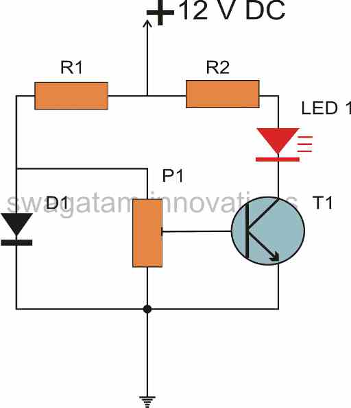
A transistor and a diode are arranged as a bridge circuit in the current architecture.

These two active components work well together since both share the same characteristics with regard to variations in the temperature around them.
Creating a Reference Voltage through a Diode
The transistor is attached to serve as a sensor for temperatures, whereas the diode serves as the reference device.
The diode definitely needs to be put in a surroundings having somewhat stable temperatures because it is used as a reference; else the diode will begin to alter its reference level, which will result in errors in the indications operation.
Here, the transistor collector is equipped with an LED, allowing it to indicate the temperature differential occurring surrounding the transistor by directly interpreting the transistor environments.
An LED Signals a Change in Temperature
The temperature level measured by the transistor is directly indicated by the LED.
In this configuration, the transistor is attached to the heat source that has to be monitored, while the diode is positioned at room temperature or ambient temperature.
At the junction of D1 and R1, the diode generates a reference voltage level that is appropriately compared to the base emitter voltage of the transistor.
For as long as the transistor's base emitter voltage stays within that threshold, it is considered to be the reference voltage level and the transistor stays powered off. As an alternative, the preset P1 can change this setting.
Now that the transistor's characteristics are changing, the base emitter voltage grows larger as the heat above it increases.
The transistor begins conducting when the temperature beyond the predetermined threshold, which is reached by the transistor's base emitter voltage.
The brightness of the LED illumination increases with time and is precisely corresponding to the temperature surrounding the transistor sensor.
Warning
The gadget may burn and sustain irreparable damage if the temperature above the transistor is allowed to rise over 120 degrees Celsius.
It is possible to further modify the suggested basic temperature indicator circuit so that it responds to measured variations in temperature by turning on or off a separate equipment.
The Temperature Sensitivity Calculation Formula
The formula below is used to compute the values of the resistors in the arrangement:
R1 = (Ub - 0.6)/0.005
R2 = (Ub - 1.5)/0.015
The BJT's forward voltage drop is expressed as 0.6, its typical working current as 0.005, and the input supply voltage as Ub.
In a similar manner 0.015 is the usual current to illuminate the LED ideally, and 1.5 is the forward voltage drop for the chosen red LED.
The values determined shall be expressed in Ohms.
P1's value might be between 150 and 300 Ohms.