
It's intriguing and really fun to build simple DIY op amp circuits with IC 741 that are provided here.
The recommended circuit concepts—which include regulated power supply, inverting and non-inverting amplifiers, and tone control—will surely pique your interest. Circuit diagrams are also included in the post.
Simple IC 741 Projects
I think most of us know about the exceptional degree of flexibility of the IC 741.
It's amazing how a few passive components integrated may result in an infinite number of possible 741 opamp circuit design ideas. Here, we investigate a few of these initiatives.
The IC 741 is one of the most versatile and multipurpose op-amps, with several configuration options.
We should look at the following descriptions of some of the important circuits for 741 opamp applications:
Inverting DC Amplifier:

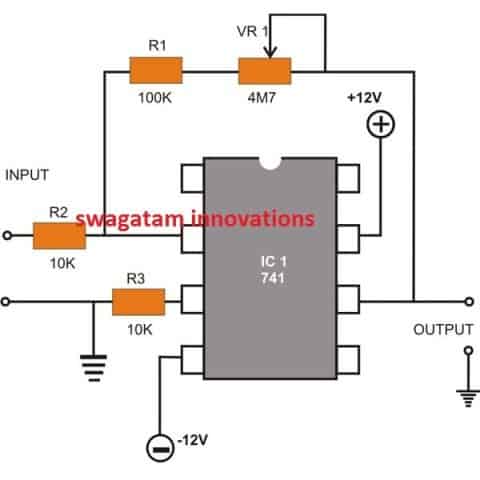
An inverted DC amplifier circuit, like the one in the accompanying figure, can be attached to the IC to occasionally amplify DC voltages.
Although the polarity would be inverted, the circuit's name suggests that a DC input will be amplified at its output. One might adjust VR1 to alter the amplifier's power.
Non-inverting DC Amplifier:

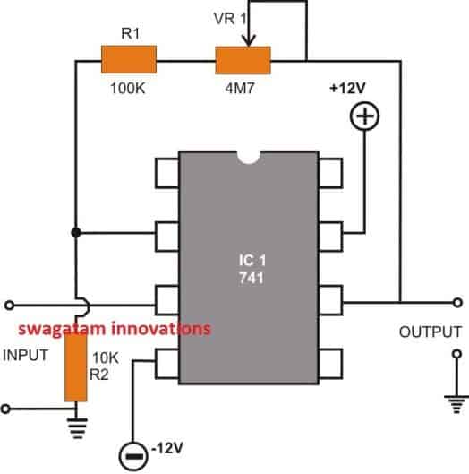
The only thing that separates this configuration from the circuit above is the output response, which stays the same regardless of the provided input voltage's polarity.
Inverting AC Amplifier:

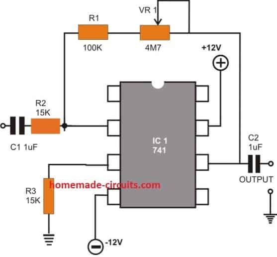
The schematic depicts the ease with which an inverting AC amplifier circuit may be constructed by modifying the basic inverting DC mode of an integrated circuit.
This circuit's goal is to enhance low frequencies by employing AC or varying input sources. C1 and C2 link the capacitors for the input and output respectively.
Using the pot VR1, the gain might also be changed in this situation.
Non-Inverting AC Amplifier:

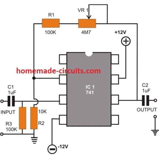
The 741 op amp circuit and the earlier discussed design differ primarily in that the first produces oscillations in phase with the input, while the second produces oscillations in opposition to the input.
Active Tone Control:

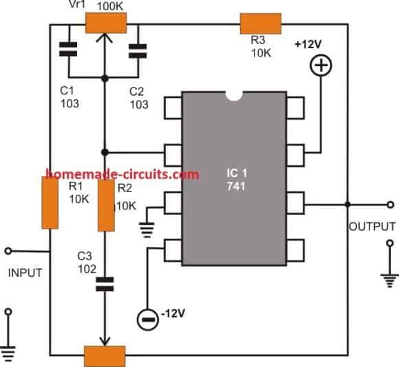
With the opamp IC741, audio frequency handling and tailoring to a particular liking could be done pretty successfully.
Anyone who wants more powerful bass in their music only has to turn the bass control shaft; those who want more treble in their song can do the same with another similar control that has been set aside for that purpose.
The circuit schematic shows how the IC 741 and a few passive parts may be used to create a basic active tone control circuit.
For the given values, the circuit produces a 12.5 dB bass boost and a 10.5 dB cut at about 100 Hz.
The treble frequency drops to 8.8 dB in proportion to the IC's adjusted gain at 1 kHz, and then to 9.8 dB at around 10 kHz. The circuit also features a high input impedance and a low output impedance.
Stabilized Power Supply Circuit Using opamp IC 741

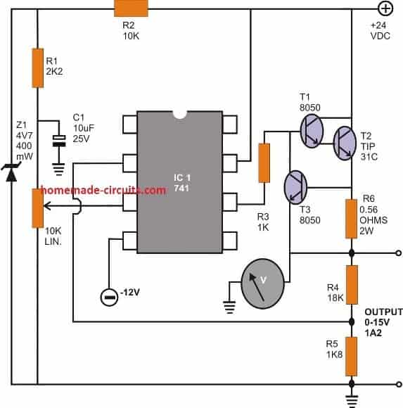
This is an example of a conventional stable voltage DC power supply based on a circuit with 741 opamps.
A cheap zener/resistor voltage reference is used to provide a reasonably steady reference to the IC's non-inverting input.
With the pot VR 1, the output voltage may be continuously changed from the minimum to its highest point of fifteen volts. A Darlington pair transistor is used at the output to boost the device's capacity to provide a large current.
To confirm whether that particular current wanders over the allowed range, T3, an extra transistor, was introduced.
The degree of adjustment might be altered by varying the quantity of resistor R6.
Power Amplifier Circuit using IC 741

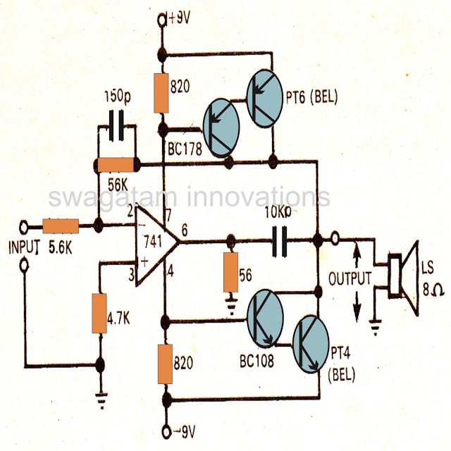
Despite having just a maximum output of 4 watts, the amplifier responds fairly well to the provided frequency.
It has a bandwidth of more than 20 kHz and less than 0.5% distortion. An input as low as 150 mV is required by the amplifier.
IC 741 Darkness Controller Relay
The darkness-activated relay may be used for many different things, including automatically flicking on an exterior or entrance light or dimly illuminating a kid's sleeping area at night.
In other words, as soon as darkness falls on the LDR, the relay is activated. If the appliance you wish to turn on through the relay is low voltage, use a relay with low voltage interfaces.

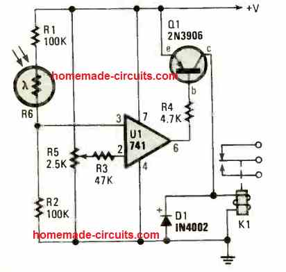
If you would like your appliance to use more power, pick a relay with terminals which can control the voltage (and current) equivalent to the appliance's capability.
That's how easy it truly is. Just make sure the relay coil has a rating of at least 150 ohms. The R6 LDR will have minimal resistance under average lighting.
There will be an elevated input voltage at pin 3 of IC U1, which will lead to a high output at pin 6.
Since transistor Q1 is a PNP transistor, the collector current may be reduced for as long as pin 6 of the IC 741 keeps its base positive.
When the amount of light provided to the LDR decreases or darkness approaches, the R6 LDR resistance increases.
The output of IC 741 at pin 6 becomes low or close to zero voltage in this scenario because Pin 3 of the IC 741 shifts in the reverse direction.
In this case, the 4k7 resistor, R4, provides the necessary negative base current to Q1 base. The transistor's collector current now rises, quickly activating the relay. Any associated load, including a lamp, goes on as soon as the relay is engaged.
741 Touch Switch Circuit
The IC 741 touch switch circuit is a sensitive feel-operated switch that can additionally be utilized as a rainfall sensor if required.
As can be observed in the picture, Pin 3 of the IC 741 is stabilized by resistors R1 and R2. By inverting the input (pin 2) and traveling to the preset R3's adjustable arm, you can tweak the trigger threshold.
As soon as the tip of the finger hits the sensitive plate, Pin 2 of the IC 741 goes negative, linking alternating, parallel copper strips. As a result, pin 6 of the IC 741 becomes positive and the effect is amplified.

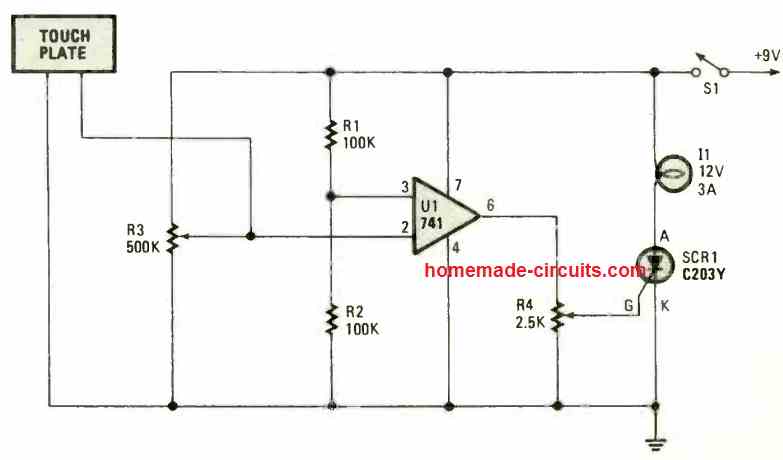
Normal operating circumstances maintain the SCR in the switched-off position, which turns off the lightbulb.
When the touch plate is contacted, Pin6 turns positive, which causes the SCR gate to turn positive as well. The bulb then turns on as a result of the SCR firing, working, and latching, and it stays on as long as S1 turns off the circuit's electric power supply.
Proximity Sensors using IC 741
The proximity sensor below uses the noise created by the 50 or 60 Hz AC interference that surrounds us. The main working element in the circuit is an IC 741 op-amp.

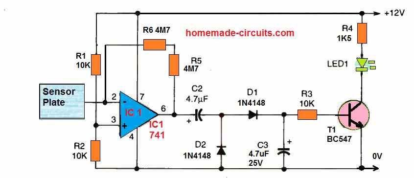
By wiring a couple of 4M7 feedback resistors between the negative input at pin 2 and the output at pin 6, the amplifier's gain may be practically increased to 100%.
Pin 2 is the input, and it is advised to place the metal pick-up detector next to the IC circuitry.
The output of the amplifier passes via a detector/rectifier circuit before the BC547 NPN transistor's base is given a positive working voltage.
As soon as the transistor senses a particular thing, the LED is turned on. For this type of acoustical pickup circuit, the sensor has to be no bigger than a half-dollar coin.
Should the sensor plate is overly large, there's a chance that ambient noise will cause an incorrect triggering. Just position your hand anywhere near the detecting plate to activate it.
If you tried to use this circuit somewhere else without being connected to the mains AC energy, the gadget would probably stop working properly.
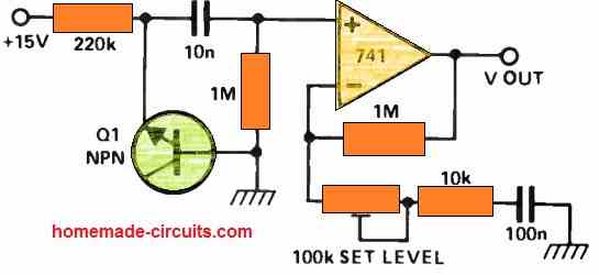
Proximity Sensor that does not Depend on Mains 50 Hz Hum
The identical 741 op-amp might be used in a different circuit which does not depend on an outside AC signal supply (e.g. an AC 50/60 Hz hum).
This article describes a very special proximity sensor device that uses a 741 op-amp in a high frequency oscillator circuit that operates near to its peak frequency.

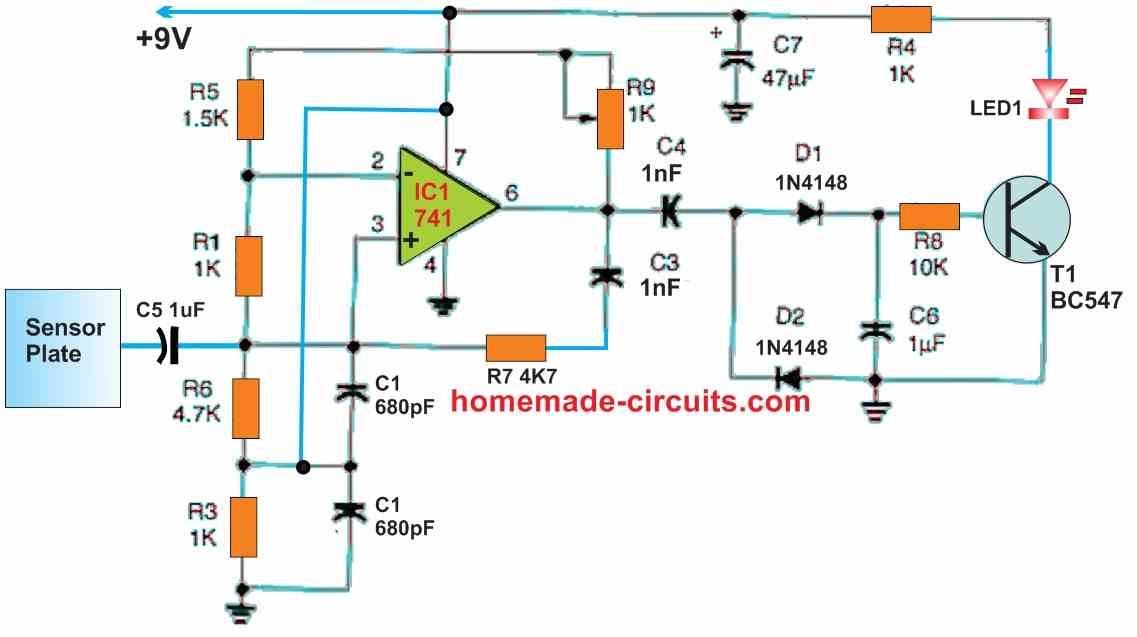
The 741 op-amp's own internal feedback capacitor sets a maximum frequency limit.
The gain of the op-amp drops with frequency until it is just barely more than one. Enhancing the frequency to the proper threshold causes the feedback process of any load-type proximity sensor circuit to become extremely load responsive.
The frequency is determined by the C1, C3, R6, and R7 elements of the oscillator.
The feedback resistors, R5 and R9, control the gain. One benefit of not being dependent on a certain supply voltage for an op-amp is that its bias could be altered through R2 and R3 to produce a DC output at fifty percent of the voltage applied to pin 6.
We may benefit from the maximum allowable output-voltage variations by operating the output at half supply. Any voltage in the range of 9 to 16 volts will function.
The rectifier circuit, which is supplied by pin 6 of the oscillator, is made up of D1, D2, C4, and C6.
The rectifier's positive output illuminates the LED and activates Q1. R9 must be set to the point wherein the LED has barely begun to illuminate in order to get greatest sensitivity.
When your hand is two to three inches away from the metal detector, a 4-by-6-inch area shielded from nearby targets may detect your proximity.
Using larger plates might result in an expanded sensing distance.
The sensor plate's size establishes the highest possible area of surface that permits circuit oscillation.
Excessive size or proximity to a ground mass may prevent the circuit from oscillating. The negative supply of the sensor must be connected to either ground or a sizable metal item that may create capacitance with ground.
Dual Power Supply
Using a voltage divider, that offers a low impedance center tap with a single supply, is one method to create dual symmetrical supplies as opposed to building separate duplicate supplies and joining them in series.
Use of an existing workstation power supply that is supplied by a voltage divider like the one seen in the circuit diagram is recommended.

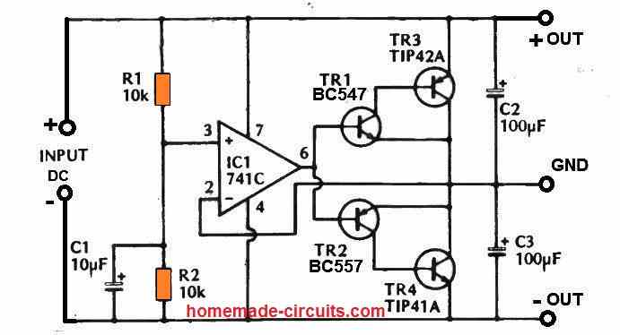
The proposed circuit functions optimally with supply voltages from 15V to 30V as each output supply line has a voltage that's approximately 50% the input voltage (i.e., 30V will be needed at the input to create +/-15V outputs).
The Tr3 and Tr4 transistors are easily able to tolerate currents up to 100 mA, therefore mounting them on heatsinks may not be essential.
A class B output stage featuring a minimal output impedance plus an increased input impedance make up the two power supply circuit, which is basically a unity gain amplifier.
A class B output stage is used because it allows the circuit to operate with a small quiescent current draw (not reaching 2mA). Tr1 and Tr3 are transistors that are set up as common emitters.
However, given that they deliver 100% negative feedback from Tr3's collector to Tr1's emitter, they only produce a unit gain. Tr1 and Tr3 are paired as complementary outputs with Tr2 and Tr4.
Notch Filter Circuit
An continuous noise can be rather bothersome while experimenting with analog signals.
In most cases, an active filter effectively removes this unwanted noise in these types of situations; this process is called "notching."

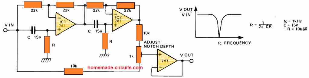
With an IC 741 op amp focused active filter, one can precisely match the frequency of the undesired sound, allowing for regulated signal attenuation.
This technique is frequently used, for instance, to get rid of mains hum from a specific location.
Here's how the circuit functions:
Together, the two ICs form an all-pass filter. These filters have a flat frequency response, nevertheless they phase shift as the frequency increases.
With a frequency of 1/2CR Hz, they are capable of a 180° phase shift, and at the highest feasible frequency, a 360° phase shift. The signals are inverted in this band of frequencies.
Thus, combining the phase-delayed signal with the initial signal can achieve termination and result in a distinct notch in the frequency response.
To obtain the most powerful notch possible, a setting is utilized. Furthermore, the operating frequency could be modified by adjusting the two resistors, R.
For instance, in order to operate at 50 Hz, R must be set approximately 220 kΩ.
Noise Generator
The distinctive zener breakdown characteristics in a transistor junction are a helpful contributor to noise for various circuit applications.

A a small amount, inherently random noise voltage is produced as a result of this uncontrollably occurring zener breakdown phenomenon. Additionally, the source impedance of this noise voltage is significant.
To effectively handle this noise, an IC 741 operational amplifier—an component with a large input impedance and substantial AC gain—is employed.
This configuration may be used to construct a low impedance noise generator that generates detectable noise signals.
The noise level is regulated via a programmed preset, which makes it possible to accurately modify gain across a 20–40 decibel range.
Telephone Amplifier Circuit
Playing music on your cell phone at loudspeaker volume without physically attaching it to the device is possible with the aid of the IC 741-based audio amplifier stated earlier.

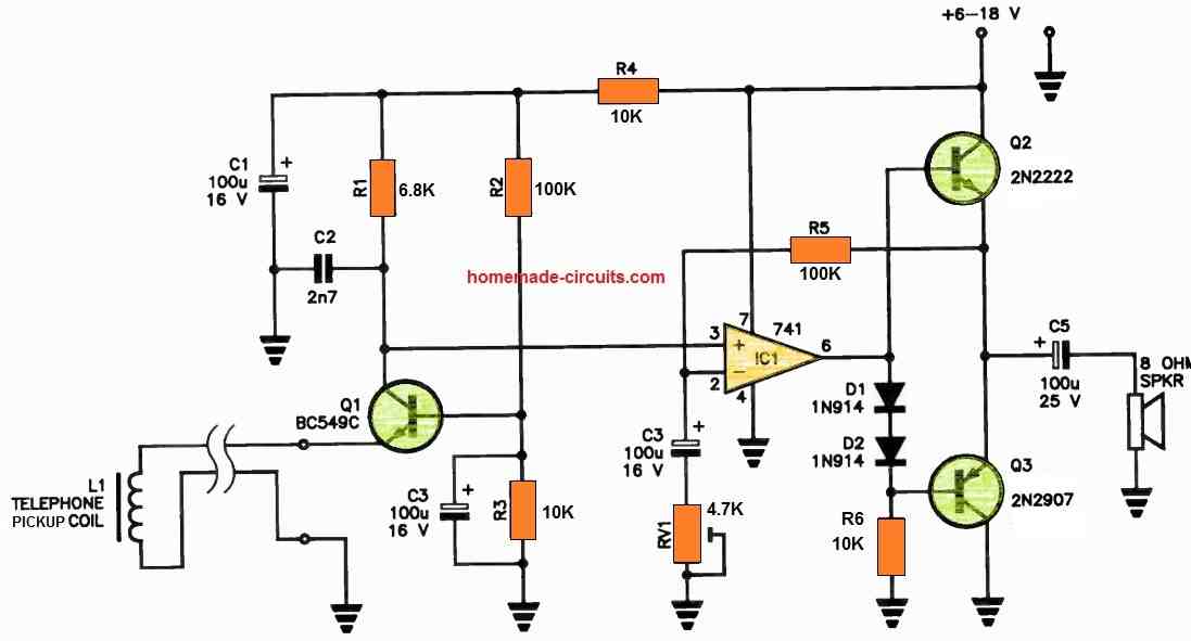
For this kind of setup, a telephone pickup coil—which is easily obtained from electronics retailers—is needed. This coil is often mounted beneath the phone, beside the line hybrid transformer, or behind the earpiece part of the telephone.
The phone's audio output generates signals which are received by the coil, known as L1. These signals are subsequently amplified by Q1, which functions as a common-base amplifier.
The collector of Q1 is directly linked to the non-inverting input of IC1. The output of IC1 drives Q2 and Q3, the base inputs of the complementary transistor output stage.
This clever arrangement allows for efficient phone audio amplification without requiring a direct connection to the telephone handset itself.
As the amplification cutoff is adjusted by RV1, resistor R5 produces feedback. It is the duty of R2-R3 to provide Q1 with the necessary bias.
C3 serves as an AC bypass at the base of Q1, ensuring the proper signal path. Simultaneously, C2 assists in high-frequency roll-off, effectively blocking unwanted side signals.
Because they create base bias isolation for the class B designed output stage devices, D1 and D2 are essential components of the circuit.
This versatile gadget may be powered by a DC voltage that can supply 6 to 18 volts. It is quite amazing that it generates 1 to 1.5 watts of electricity.
When picking a speaker, it's crucial to remember that larger loudspeakers usually work far more effectively than smaller ones, ensuring the highest quality audio output.
Switching ON/OFF Timer Circuit using IC 741
This circuit is a fantastic way to create an automatic ON/OFF repeated timer for use in displays or slide-show presentations.

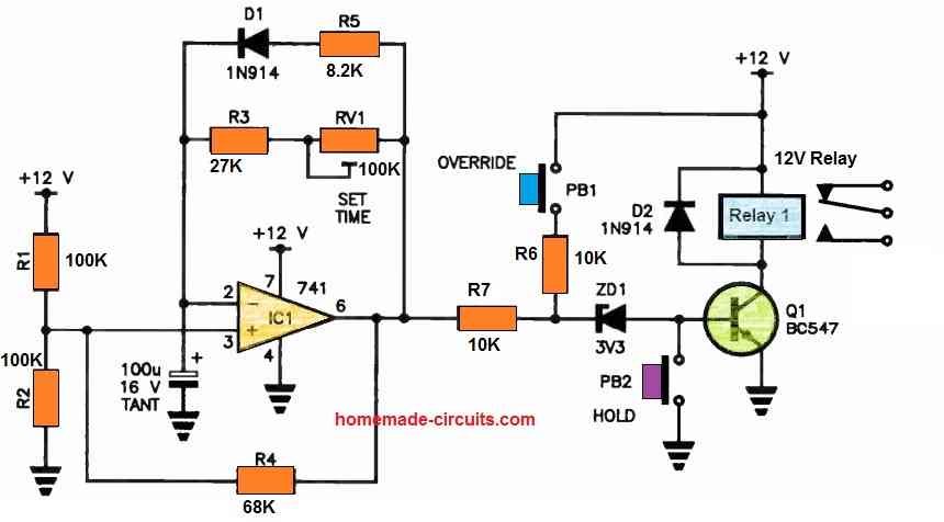
The feedback loop system's diode allows IC1, represented by IC741, to function as a square wave oscillator that has a lengthy cycle period of time and a relatively small mark-to-space ratio.
To enable its output to oscillate between near the positive voltage rail and toward ground, IC1's non-inverting input is biased to around 50% of the supply voltage.
When the output voltage reaches a certain level, IC1 activates Q1, which then turns on the relay.
The range of variation for the time duration between each of these pulses, which is about five to thirty seconds, is determined by RV1. The period for which the relay remains functioning is determined by R5.
The circuit features two buttons—an Override key and a Hold key—for increased efficacy.
The Overriding button simply has to be hit once for manually turning on the relay in between the automatic pulses. Another choice is to utilize a pushbutton that performs a quick operation.
On the other hand, the relay can't work during the time as the Hold button is down.
Linear Ohm Meter Circuit
Unless you want to spend a lot of money on one, a linear scale ohmmeter is far more useful than a digital multimeter.

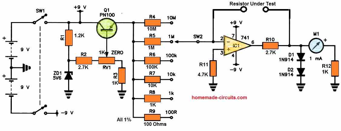
This will result in a lower cost!
Q1 and a few of the various resistors [R4 to R9] make up a constant current source that feeds a steady current into the op-amp IC1's inverting input.
It is necessary to inspect the resistor which has been connected between the inverting input and output of the op-amp.
The output voltage is determined by dividing the selected range resistor value by the unknown resistance.
R10 restricts the maximum output current of IC1, whereas diodes D1 and D2 lessen pounding of the meter pointer by lowering the voltage throughout the meter circuit.
Bypassing all of that and just getting Class 2 meters—which are expensive and difficult to locate yet offer an incredible 2% measurement precision—is perfectly acceptable. A range resistor can have a value of 1% or 2%.
It is possible to simultaneously zero the meter and adjust the source current with RV1. You could energize the circuit with a couple of 9 V transistor radio batteries.