
New hobbyists may find it interesting to try the following DIY multimeter circuits as their next electronic project, as they require a multimeter for testing and debugging electronic project circuits.
How to Use Opamp 741
The following section discusses a few opamp-based meter circuits that use the IC 741 plus a few additional passive parts, such as an ohmmeter, voltmeter, and ammeter.
Despite the abundance of multimeters on the market today, creating your own DIY multimeter may be a lot of fun.
The characteristics involved may also prove to be extremely beneficial for next electronic circuit testing and construction processes.
DC Voltmeter Circuit using IC 741

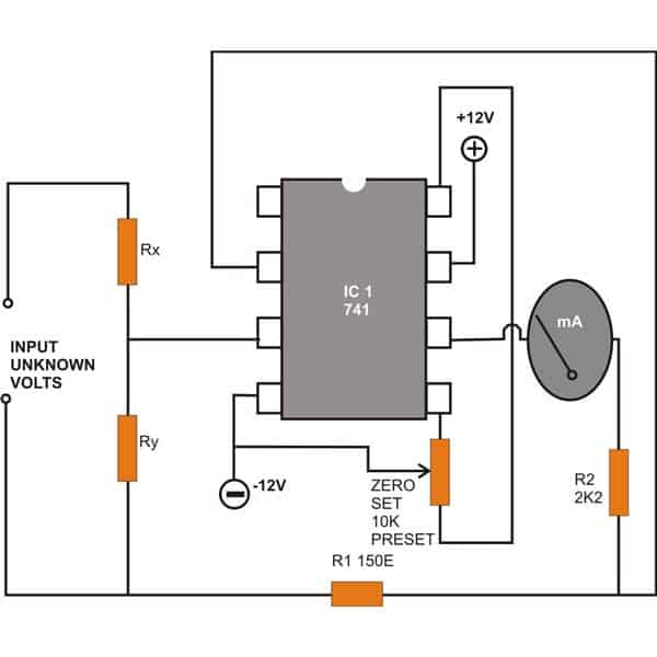
Note: The zero-set preset's bottom end is connected to pin #8 of the IC by mistake; please connect it to pin #1.
The IC 741 is used in the straightforward setup for monitoring DC voltages that is seen above.
At the non-inverting pin #3 of the integrated circuit, two resistors, Rx and Ry, are inserted at the input in a potential divider mode.
Applying the voltage between resistor R1 and ground allows for measurement.
The meter's range may be adjusted, allowing for the measurement of various voltages, by carefully choosing Rx and Ry.
AC Voltmeter Circuit using IC 741
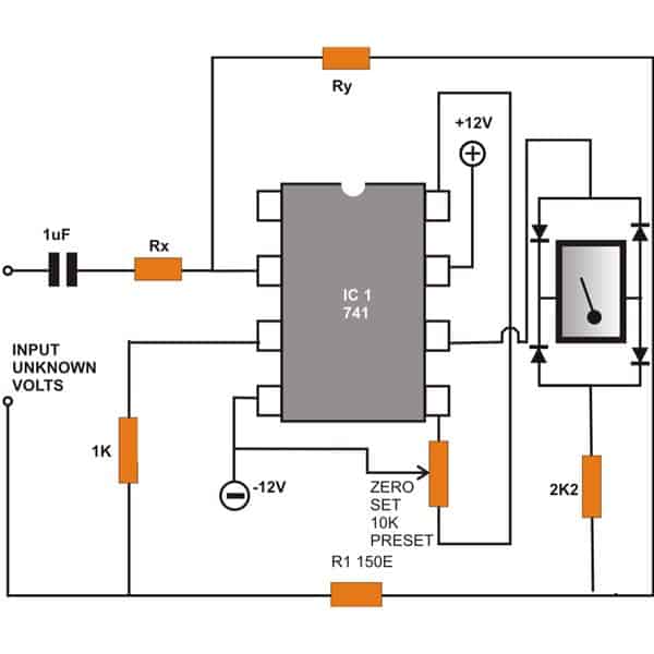
Note: The zero-set preset's bottom end is connected to pin #8 of the IC by mistake; please connect it to pin #1.
The circuit shown above might be helpful if you wish to test alternating voltages.
Although the locations of Rx and Ry have changed and a coupling capacitor is introduced at the IC's inverting input, the wiring is identical to the wiring shown above.
It's interesting to note that this meter can now accurately display the pertinent AC potentials because it is connected across a bridge network.
DC Ammeter Circuit using IC 741
The next image shows another setup that uses the IC 741 to measure direct current or amps.
It appears that the configuration is quite straightforward. Here, the input is applied across the resistor Rz, or between ground and the IC's non-inverting input pin #3.
Changing the resistor Rz's value is an easy way to adjust the meter's range.
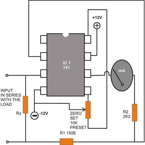
Note: The zero-set preset's bottom end is connected to pin #8 of the IC by mistake; please connect it to pin #1.
Ohmmeter Circuit using IC 741
One of the most crucial passive parts that are unavoidably included in any electrical circuit are resistors.
Building a circuit without these incredible current-controlling tools may be next to impossible.
Given the large number of resistors used, a potential malfunction is always conceivable.
An Ohm meter is needed to identify them. For this aim, a basic design utilizing the IC 741 is presented below.
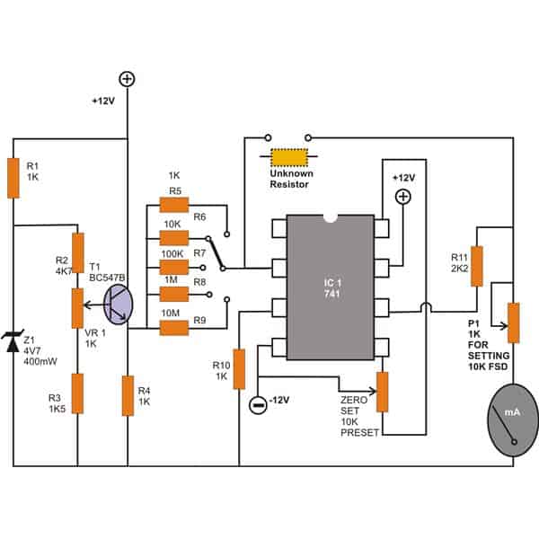
Note: The zero-set preset's bottom end is connected to pin #8 of the IC by mistake; please connect it to pin #1.
The current design effectively addresses the issue of producing a fully linear response with the appropriate measurements, in contrast to the majority of analog systems that have a tendency toward somewhat non-linear behavior.
Its measurement range is fairly astonishing, ranging from 1K to an astounding 10 M for resistor values.
Further modifications to the circuit can be made to allow for the measurement of even more extreme values.
By adjusting the rotary switch switch to the appropriate locations, the range may be chosen.
Setting Up the IC 741 Meter Circuits
The following points are used to complete an easy calibration of the instrument: Set the "10K" position on the selector switch.
Using a digital multimeter, trim the transistor's base setting until the emitter voltage reads precisely 1 volt. Then, insert a precisely calibrated 10 K resistor into the measurement slot.
The moving coil meter's trimmer should be adjusted until the meter displays a full scale deflection.
Every circuit covered above makes use of two supply voltages. The meter in use is a moving coil type with a 1mA FSD specification.
To set the initial condition meter to precisely zero, place a preset across pins 1, 4, and 5 of the IC 741 that powers this homemede multimeter. Rx and Ry's Relevant Values These resistor values are necessary to adjust the range of the corresponding meters.
DC Voltmeter
| Rx | Ry | Meter FSD |
|---|---|---|
| 10M | 1K | 1KV |
| 10M | 10K | 100V |
| 10M | 100K | 10V |
| 900K | 100K | 1V |
| NIL | 100K | 0.1V |
DC AMMETER
| Rz | Meter FSD |
|---|---|
| 0.1Ω | 1A |
| 1Ω | 100mA |
| 10Ω | 10mA |
| 100Ω | 1mA |
| 1kΩ | 100uA |
| 10kΩ | 10uA |
| 100kΩ | 1uA |
AC VOLTMETER
| Ry | Rx | Meter FSD |
|---|---|---|
| 10K | 10M | 1KV |
| 100K | 10M | 100V |
| 1M | 10M | 10V |
| 1M | 1M | 1V |
| 1M | 100K | 100mV |
| 1M | 10K | 10mV |
| 1M | 1K | 1mV |