The construction of an RTD temperature meter circuit is covered in this post, along with information on various RTDs and how they operate mathematically.
What's an RTD
When exposed to heat, the resistance of the sensor metal changes or increases, which is how an RTD, or resistance temperature detector, operates.
A precise determination of the applied temperature range is possible since the element's variation in temperature is directly related to the amount of heat.
Both the operation of RTDs and a basic circuit for a high temperature sensor created with a DIY RTD device are explained in this article.
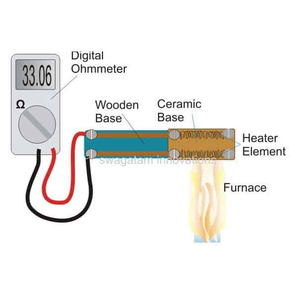
Through heating a regular "heater coil" or a "iron" element, an immediate indication in the form of variable resistance values may be achieved.
Because resistance is directly proportional to heat applied, it matches applied heat and may be measured using a standard digital Ohm meter. Find out more.
Understanding RTD Temperature Meters Working
One basic characteristic shared by all metals is their ability to alter their resistance or degree of conductivity when subjected to heat or increasing temperatures.
When a metal gets hotter, its resistance rises and vice versa. RTDs take advantage of this feature of metals.
Given that the aforementioned fluctuation in the metal's resistance clearly corresponds to electric current, a metal that is exposed to temperature changes will provide equivalent degrees of resistance to the applied current.
This means that the current likewise fluctuates proportionally with the metal's changing resistance; the current output fluctuation can be directly determined using a meter that has been set up correctly.
In essence, an RTD temperature meter works as a thermal transducer or sensor in this way.
RTDs are frequently defined in terms of resistance, which implies that at zero degrees Celsius, the element should exhibit resistance of 100 Ohms.
Since platinum has excellent metallic properties such as stability (the capacity to withstand high temperatures and prevent abrupt modifications), massive resistance temperature coefficient, favorable linear response to temperature versus resistance gradient, and invulnerability to chemicals, platinum is typically used in RTDs.

RTD Elements
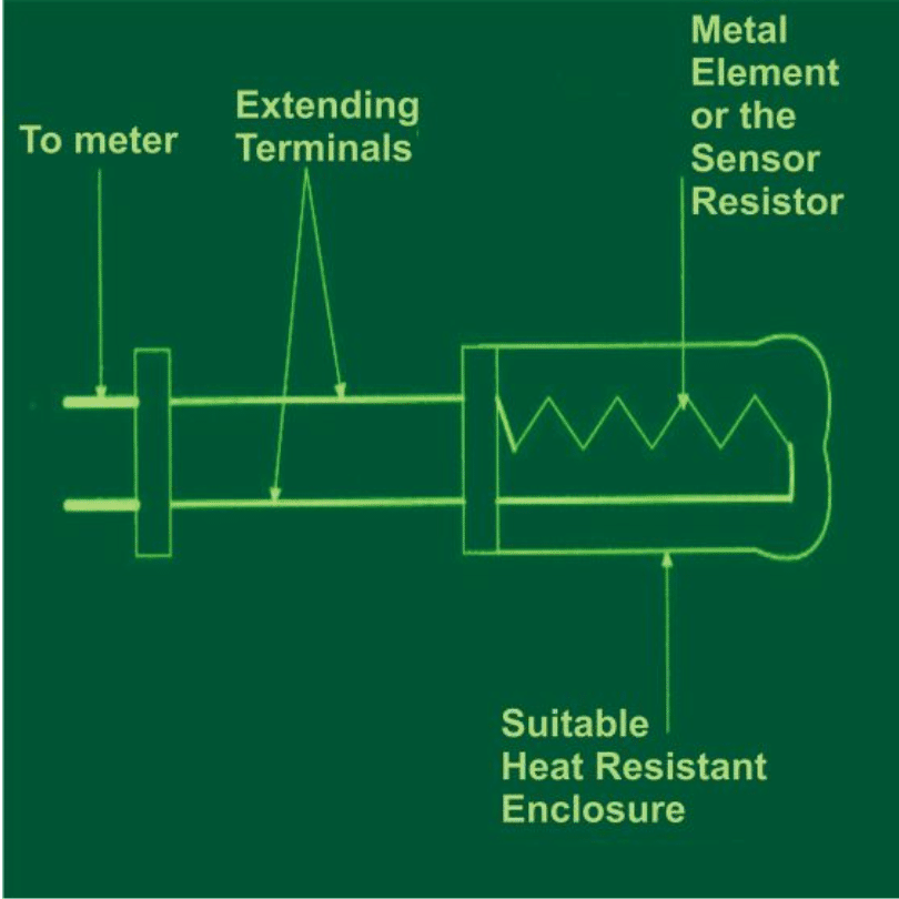
The fundamental layout of a typical RTD device is seen in the above illustration of a typical RTD temperature meter. It's a straightforward kind of thermal transducer with the following primary parts:
an outside casing which is outwardly sealed and composed of a heat-resistant component like metal or glass.
A thin metal wire that serves as the heat-detecting element is enclosed in the casing above.
A couple of exterior flexible wires serve as the element's termination point and supply current to the encased metal element or transducer.
Inside the container, the wire element is carefully positioned to be evenly distributed over its entire length.
Understanding Resistivity
The essential idea behind RTDs is that the majority conductors exhibit a linear fluctuation in their inherent characteristic—that is, resistance or conductance—when exposed to different temperatures.
The metal's resistance is exactly what alters most with temperature.
Resistance temperature coefficient, often known as alpha, is the word used to describe the fluctuation in a metal's resistivity that corresponds to applied temperature variations. It may be represented using the equation as follows:
alpha = d(rho)/dT = dR/dT ohms/oC (1)
where R represents the element's resistance in Ohms with a certain arrangement, and rho is the element's or the wire metal used.
Calculating Resistivity
Using the generic formulation of R found in the formula that follows, the above method may also be used to get the temperature of an arbitrary system:
R = R(0) + alpha (0 degree + Tx), where R(0) depicts the resistance of the sensor at zero degree Celsius whereas Tx denotes the temperature of the element.
The above equation can be further simplified as given below:
Tx = {R – R(0)}/alphaTherefore, when R = R(0), Tx is = 0 degree Celsius, or when R > R(0), Tx > zero degree Celsius, however at R > R(0), Tx < 0 degree Celsius.
It is crucial to remember that, in order to use RTDs with accuracy, the applied temperature needs to be evenly spread throughout the whole length of the sensing element; otherwise, the output might contain readings which can be unpredictable and erroneous..
Types of RTDs
Though a two-wire RTD is never exact because of several operational limitations, the requirements listed above pertain to how a two-wire type basic RTD functions.
Usually, a wheatstone bridge or other extra circuitry is added to the device to increase its accuracy.
Both 3-wire and 4-wire RTD types can be applied to these devices.

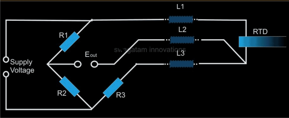
Three Wire RTD:
Typical three-wire RTD connections are depicted in the diagram above. In this instance, L3 acts like a potential lead while the measuring current passes via L1 and L3.
Since L1 and L3 are in different arms of the wheatstone network, the resistances become neutralized and acquire a high impedance across Eo for so long as the bridge is in the balanced condition. Additionally, the resistances between L2 and L3 are maintained at the same levels.
The setting guarantees that, while maintaining an accuracy within 5% of acceptance levels, no more than of 100 meters of wire may be terminated between the sensor up to the receiving circuit.

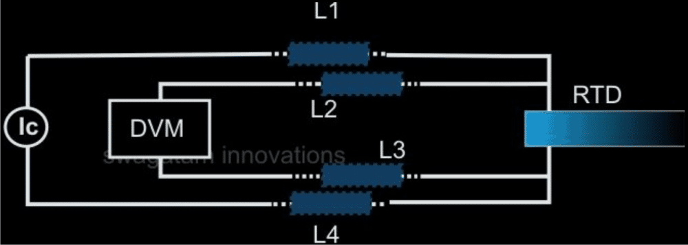
Four Wire RTD
Regardless of whether the real RTD is positioned at a considerable distance from the visual display, the four wire RTD is arguably the most effective method for obtaining precise data.
By eliminating any lead wire inconsistencies, the technique generates incredibly precise readings. The RTD is operated on the basis of a continuous current being supplied through it, and the voltage across it is measured using a high impedance measuring instrument.
The approach produces far more trustworthy results while doing away with the need for a bridge network.
A standard four-wire RTD wiring scheme is seen in the above picture. Using L1, L4, and the RTD, a strictly calibrated constant current drawn from an appropriate source is applied.
No matter how far away the high impedance DVM is relative to the sensing element, it can determine a corresponding result that is readily accessible across the RTD via L2 and L3.
The resistances of the wires, L1, L2, L3, and L4, now become negligible values which have little impact on the actual measurements.
High Temperature RTD Sensor Construction
It is possible to create a high temperature sensor unit utilizing a standard "heater element," such as a heater coil or "iron" element. The foregoing talks serve as the foundation for the operational concept.
All that has to be done is build the connections as the DIAGRAM shown below illustrates.