
Furnaces are chambers used in industrial operations such as metalworking, which are designed to create extremely high temperatures. In many applications, precise temperature control is essential since variances might have a detrimental effect on the finished product or even pose a safety risk.
The application of thermocouples in furnace temperature measuring circuits (pyrometers) is examined in this article. Strong sensors called thermocouples are made especially to endure the intense heat that exists in ovens and furnaces.
Simple and reliable circuits based on thermocouples are available for detecting high temperatures in furnaces. This idea is shown in the provided circuit design.
Furnaces: From Household to Commercial
There are many different types of furnaces, ranging from big industrial facilities to boilers used in homes. Precise temperature control is less important because the main purpose of home furnaces is to provide warmth.
Accuracy Counts in Industrial Environments
In contrast, industrial furnaces operate with metalworking operations, where even minute temperature changes can have a big impact on the final product. Thus, it is imperative in these situations to have constant and precise temperature monitoring, which is frequently accomplished electronically.
Understanding the Seebeck Effect: Electricity from Heat
Thomas Johann Seebeck, a scientist, made the intriguing discovery of a phenomena in 1821. He noticed that an electric current runs through a system when two distinct metals are linked at their ends to produce two junctions—one hot and one cold.
Seebeck's breakthrough came from witnessing a compass needle distort in close proximity to the metals. This deviation suggested that there was an electric current flowing.
It's noteworthy to note that two more comparable phenomena, the Peltier effect and the Thomson effect, were subsequently discovered and named after different scientists. These phenomena involve temperature variations influencing the electrical characteristics of materials.
Inside a Thermocouple: Turning Heat into Electricity
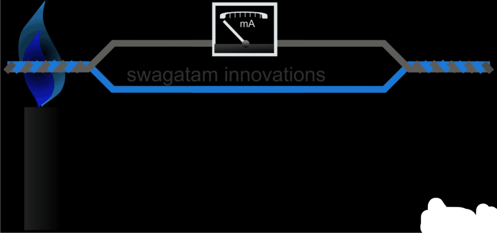
Let's investigate the conversion of heat into electricity using a thermocouple sensor. Consider the following scenario: two distinct metals, such as copper and aluminum, are twisted together at one end to create a junction (see diagram). This intersection is known as the measuring intersection.
Currently, an intriguing phenomenon occurs when we raise the temperature of the measuring junction while maintaining the reference junction at normal temperature. The Seebeck Effect causes a very little electric current to pass through the loop that the two metals form.
As seen in the picture, we can easily confirm this current by simply connecting a milliampere in series with the loop at any point along the wires. When current flow is present, the milliammeter will deflect.

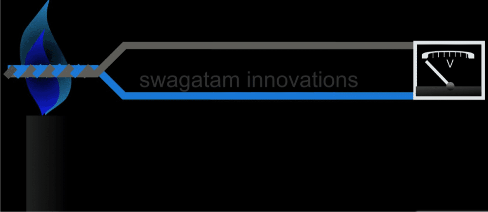
The milliammeter we previously used can be used to measure the current passing through the thermocouple circuit, but it is unable to determine the voltage, or electrical pressure, that exists between the two wires.
Because the voltage produced by thermocouples is often rather modest, we need a voltmeter, more specifically, a millivoltmeter, to measure this value. The wiring diagram illustrates how to connect a voltmeter in order to measure voltage.
Observe how the schematic joins the exposed wires to the voltmeter's terminals at the second junction, which is the reference junction. In this manner, the thermocouple's two metals' voltage differences are measured by the voltmeter.

For measuring high temperatures, the guidelines and concepts mentioned above seem like a simple and uncomplicated solution.
Weaknesses of Thermocouples: Keeping Things Simple for Precise Readings
Thermocouples work extremely well for measuring high temperatures, but one drawback is that their accuracy depends on the temperature differential between two junctions. The readings may become inaccurate if the system has any more intersections.
Envision attaching the terminals of your meter to the wires of the thermocouple. These connections, which resemble small undesired junctions, produce new temperature measuring locations.
Your results may be off because the temperature at these additional connections may be higher or lower than the real temperature you're attempting to measure.
Short leads and a simple approach help to reduce errors.
Although the additional junctions brought about by meter connections may lead to mistakes, their effects can be reduced. It is helpful to keep the meter wires relatively short. In an ideal world, the thermocouple ends would be directly connected to the meter, negating the temperature differential at these additional junctions.
But since more intricate techniques, such utilizing a Wheatstone bridge circuit, may produce even more precision, this strategy is frequently ignored.
On the other hand, simplicity is essential for our small experiment. By connecting the short meter wires straight to the thermocouple terminals, we can reduce the amount of mistakes. For our needs, this method provides a fair compromise between simplicity and sufficient precision.
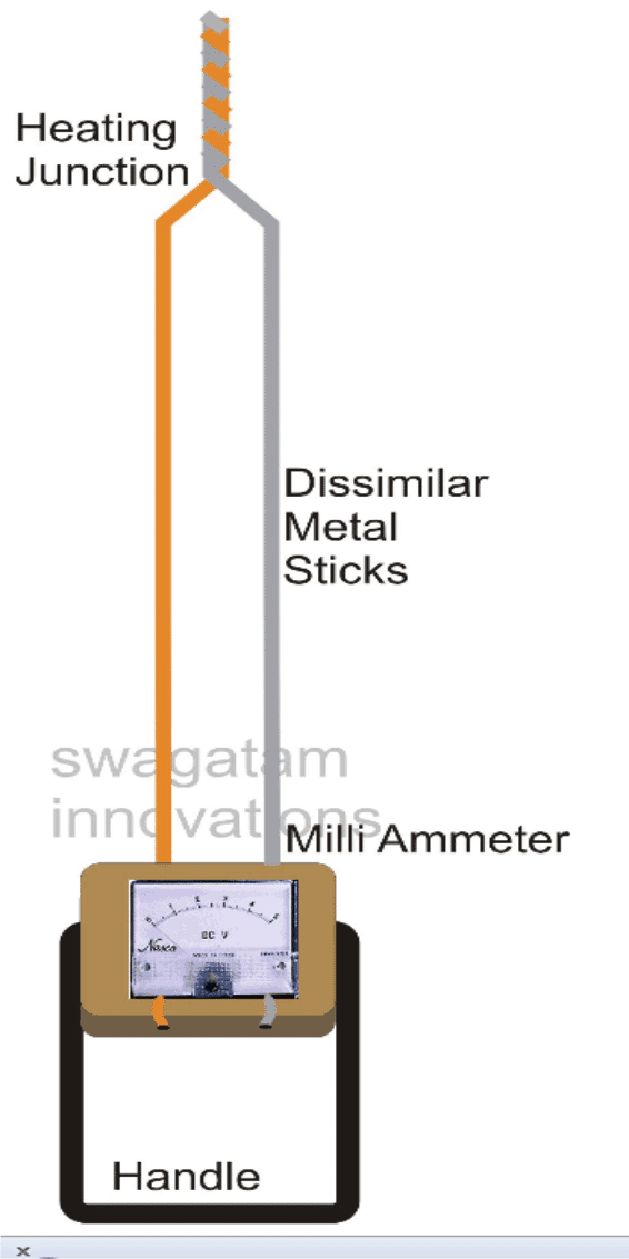
In order to safely insulate the meter from the furnace heat and yet obtain a relatively accurate reading of the measured temperature, we use a very odd but extremely successful approach of choosing long bars of the two different metals.
Building Your Pyrometer: A Step-by-Step Guide
In this part, you will learn how to build a pyrometer that measures furnace temperatures using a thermocouple sensor.
Assemble Your Materials:
Make sure you have all the required parts before we start:
Two metal rods, measuring 2.5 feet in length and 0.5 cm in diameter—one made of copper and the other of aluminum.
A milliammeter (moving coil type, 1 mA full-scale deflection)
A wooden block with handles that has holes pre-drilled for the metal rods
You may design the pyrometer circuit and assemble the thermocouple by following these instructions.

Getting the thermocouple ready:
Cleaning: Begin by using sandpaper to clean the aluminum and copper rods. By doing this, any oxidation, corrosion, or debris that might harm the connection is removed. For both metals, strive for a glossy, brilliant finish.
Bend and Twist: As indicated by the diagram, carefully bend the metal rods at an angle. Twist the clean ends tightly together using needle-nose pliers. In order to monitor temperature differences, this generates the thermocouple junction.
Securing the Junction: The recently created intersection is fragile. We'll strengthen the rods' free ends to safeguard it. How to do it is as follows:
Locate a block of wood that has holes bored through it. The diameter of the rods and the holes should be almost equal.
Carefully insert the rods with the twisted connection through the wooden block's pre-drilled holes. For the connection to be firmly held in place, the fit must be tight.
Installing and calibrating the meter:
Meter Positioning: Tighten the ammeter into a proper position on the wooden block.
Thermocouple connection: Attach the free ends of the aluminum and copper rods to the appropriate ammeter terminals (not the twisted junction).
Important Note: To really calculate the temperature, we actually need a voltage value, however the ammeter that is given measures current.
To deal with this, there are two choices:
First option: Installing a Resistor: We may install a precisely measured resistor across the terminals of the ammeter. In doing so, the thermocouple's current will be transformed into a voltage that the meter can display. However, this method may not be the best for novices as it needs careful resistor selection.
Option 2: Calibration: It is possible to directly show temperature by recalibrating the ammeter scale itself.
This entails measuring the current at a known temperature while utilizing a source of reference temperature, such as a boiling water bath.
After that, you may record temperature values on the meter scale that match the current measurements that were measured. This method provides a simpler way for a basic experiment, although it is less exact than using a resistor.
Recall that in order to convert current data into useful temperature values, the meter's scale will need to be calibrated, regardless of the approach you use