
Applications needing strict voltage controls and ripple rejection standards can utilize the circuit shown below. All leftover ripple factor is fully corrected thanks to the configuration of the transistor pair.
How the Circuit works
With the help of common transistors, the circuit below demonstrates how to easily create a highly stable and precisely controlled DC voltage output.
It's fairly easy to grasp the circuit, therefore let's look at it from the following angles:
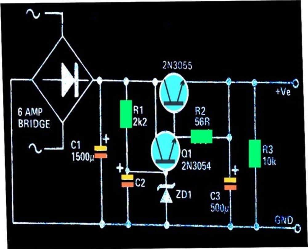
It is intended to handle currents more than 3 amps, but not more than 5 amps, using a straightforward, effective, high current 2N3055 power supply.
By adjusting R1 and the zener diode's value, the necessary voltage may be stabilized appropriately.
The voltage applied from the transformer is rectified by the diodes at the input, which are arranged in a bridge network structure.
C1 smoothes the DC even more before feeding the processed DC to Q1 and Q2's controller circuit.
By giving the transistor combination the necessary biasing, R1 is brought in to begin the circuit.
C2 ensures that the transistors obtain a ripple-free, completely clean DC at their base.
Regardless of the voltage at the input, the zener diode at the base of the Q1 pinches the transistor with a set biasing voltage and prevents any increase at the output voltage.
That is to say, regardless of how high the input voltage from the bridge network increases, the output stays the same and generates the voltage determined by the zener diode and R1 settings.

Parts List
| Component | Specifications | Quantity |
|---|---|---|
| Resistors | 1/4 watt 1% MFR | |
| 2.2 kΩ | 1 | |
| 10 kΩ | 1 | |
| 56 Ω | 1 | |
| Capacitors | ||
| Electrolytic | 1500 µF / 50 V | 1 |
| 500 µF / 50 V | 2 | |
| Semiconductors | ||
| Bridge Rectifier Diodes | 6A4 | 4 |
| Zener Diode | 1 watt, voltage value as desired between 3 V to 30 V | 1 |
| Transistors | ||
| 2N3055 | 1 | |
| 2N3054 | 1 | |
| Heat Sink | Large finned heatsink for the above transistors | 2 |
| Transformer | 0-15V, 5 amp | 1 |