
The pinout assignments and features of the well-known HOLTEK 433 MHz RF remote control module are covered in this post.

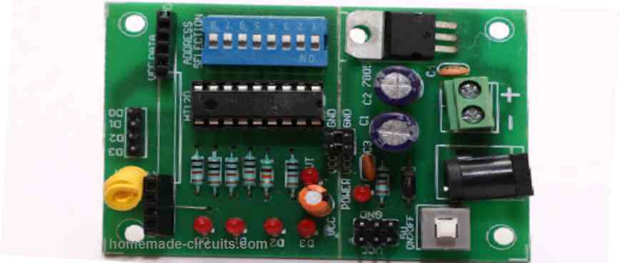
Receiver-transmitter module for remote control application operating at 315 MHz and 433 MHz
It's really simple to build your own universal remote control systems these days.
Like that After obtaining the necessary chips and assembling them, your sophisticated remote control system is now operational.
Here, we describe a few RF 433MHz remote control chips that were created expressly for this use.
The HT-12E encoder chip from HOLTEK and the IC TWS-434 combine to create a high-class transmitter circuit.
The chip RWS-434 functions as the receiver module with the help of its complementary decoder IC HT-12D.
To independently manage four external loads, the two aforementioned modules can communicate four distinct data bits.
Nowadays, it just takes a few hours to create your own global remote control modules because to the simple availability of precise remote control chips.
Here we cover a few small RF remote control transmitter and receiver modules that make use of the following chips: TWS-434, RWS-434, HT-12E, and HT-12D
It's now easy to build a high-end, professional remote control system at home. It now only takes a few hours, or better yet, minutes, to create an RF remote control thanks to the development of tiny remote control encoder and decoder circuits.
These chips may be used to create a wide range of remote controls, the best of which are for automotive security systems. You can use them to operate almost any electrical device you can imagine.
TWS-434 and RWS-434
The TWS-434 and RWS-434 are two RF remote control chips that work well together. The former is the transmitter, and the latter is the receiver.
The RWS-434 precisely complements the signals sent by the TWS-434 by receiving the coded signals and producing four distinct decoded signals at its outputs. The TWS-434 is essentially a small 4-bit transmitter module.
For the sake of the aforementioned processes, external encoders and decoders must be incorporated, though, as the two devices essentially serve as wireless transmitter and receiver.
Identifying the Pinouts of the 433MHz RF Transmitter Module
Combining TWS-434 and RWS-434 with a couple of HOLTEK's encoder and decoder chips, HT-12E and HT-12D, yields the optimal universal remote control working settings.
Using the chip TWS-434 and HT-12E, we get a simple RF transmitter arrangement (see the diagram next to this one).
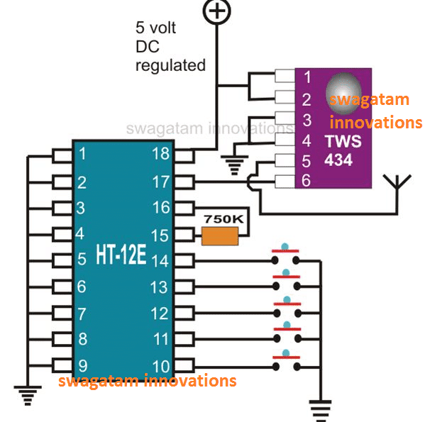
The IC TWS-434 comprises six pin outs: pins 1 and 2 are positive inputs, pins 3 and 4 are grounding, pin 6 receives 4-bit encoded signals, and pin 5 is the antenna for outputting the signals that are received.
The RF transmitter's pinout information, as seen in the picture above, may be interpreted as follows:
The IC HT-12E is used to encode data in 4 bits.
This IC has extremely straightforward wiring as well; all of its 1 to 9 pin-outs, which correspond to the address pinouts of the IC, are shorted collectively to ground.
The transmitter may produce a range of various encoded messages by configuring these 1 to 9 address pins in different ways.
An entirely new encoded output signal will result from, say, leaving one to four pins disconnected and connecting the other pins to ground. This may be achieved, for instance, by leaving one to four pins unconnected.
By choosing any desired 1 to 9 pins, you may create a multitude of unique combinations by leaving them open or connecting them to ground.
These 1 to 9 pins allow you to make several variants by connecting some of them to ground, some of them not to ground, or all of them to ground.
Keep in mind that the receiver circuit must precisely match the connection pattern made across pins 1 through 9 in the transmitter circuit in order for the two devices to function together. If they don't, they won't be compatible.
A resistor with a resistance of 750 K connects pins 16 and 15.
By connecting their individual pins to ground via a push-button switch, pinouts 10, 11, 12, and 13 are all able to receive four distinct data.
When a second push button is used to connect pin 14 to ground, it indicates that the transmitter signals have switched.
A 4-bit A/T signal is processed and sent to the IC TWS-434 for the last relay via Pin 17, which is the output. Positive supply input pin 18 is located.
Recognizing Pinouts for the 433MHz RF Receiver Module
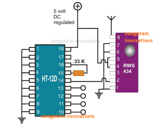
With the exact opposite transits, the figure next to it depicts a configuration akin to the one above.
The following explanation will help you understand the RF receiver module's pinout specs as displayed above:
The above transmitter module transmits data, which is received by the chip RWS-434's antenna. The IC HT-12D then uses the data to decode the 4-bit data, which is finally produced at the appropriate outputs to drive the linked loads.
It's easy to understand the IC RSW-434's pin layout: pins 1, 6, and 7 are all shorted to ground.
Pin 4 and Pin 5 connect to the positive supply.
Pin 8 acts as the antenna, while Pin 2 sends the data that has been received to the decoder IC.
The whole pin set of the decoder chip HT-12D, numbered 1 through 9, is locked to the ground potential.
According to its specifications, pin 15 is linked to pin 16 via a 33 K resistor.
After decoding the data, pin 14 receives the information that the RSW-434 has received. Pins 10, 11, 12, and 13 then get the processed data, which is then supplied to the output driving circuit to activate the associated devices.
The aforementioned universal remote control's two modules function well when powered by a regulated 5 volt unit.
Please feel free to ask any particular questions you may have through comments if you have any about the pinouts of the 433 MHz RF transmitter and receiver modules that were previously presented.